Method and system for multiple-hop relayed directional wireless communication

a wireless communication and relay technology, applied in the field of directional wireless communication, can solve the problems of poor link budget of mm-wave phy, and achieve the effect of limiting the interference impact on other neighboring stas

Active Publication Date: 2019-01-24
SONY CORP
View PDF4 Cites 3 Cited by
  • Summary
  • Abstract
  • Description
  • Claims
  • Application Information

AI Technical Summary

Benefits of technology

[0009]The present disclosure provides a mm-wave mesh network with new operating and optimization processes. More specifically, the disclosed system, apparatus and / or method provides components to improve existing routing protocols of wireless mesh networks when operated over mm-wave PHY. In addition, an approach is taught for maximizing network capacity by facilitating spectrum reuse among neighbor stations (STAs).
[0023]In mm-wave PHY, where directional transmission is used, it is possible to limit the interference impact to other neighbor STAs by selecting a proper antenna sector. Using techniques disclosed in our prior patent applications in the area of wireless directional mesh networks, it is possible for STAs to learn link quality of each antenna sector among one hop neighbor STAs.
[0025]Another aspect of this technology is to extend routing decision protocols for including both picking up proper intermediate STAs and antenna sector for use toward optimize mm-wave mesh network. Still another aspect of this technology is the ability to balance both end-end path link quality and interference impact.

Problems solved by technology

It should be noted that link budget of mm-wave PHY is still poor even with beam-formed transmission.

Method used


Image

  • Method and system for multiple-hop relayed directional wireless communication
  • Method and system for multiple-hop relayed directional wireless communication
  • Method and system for multiple-hop relayed directional wireless communication

Examples


Embodiment Construction

[0071]1. Beamforming (BF) Training in IEEE802.11ad

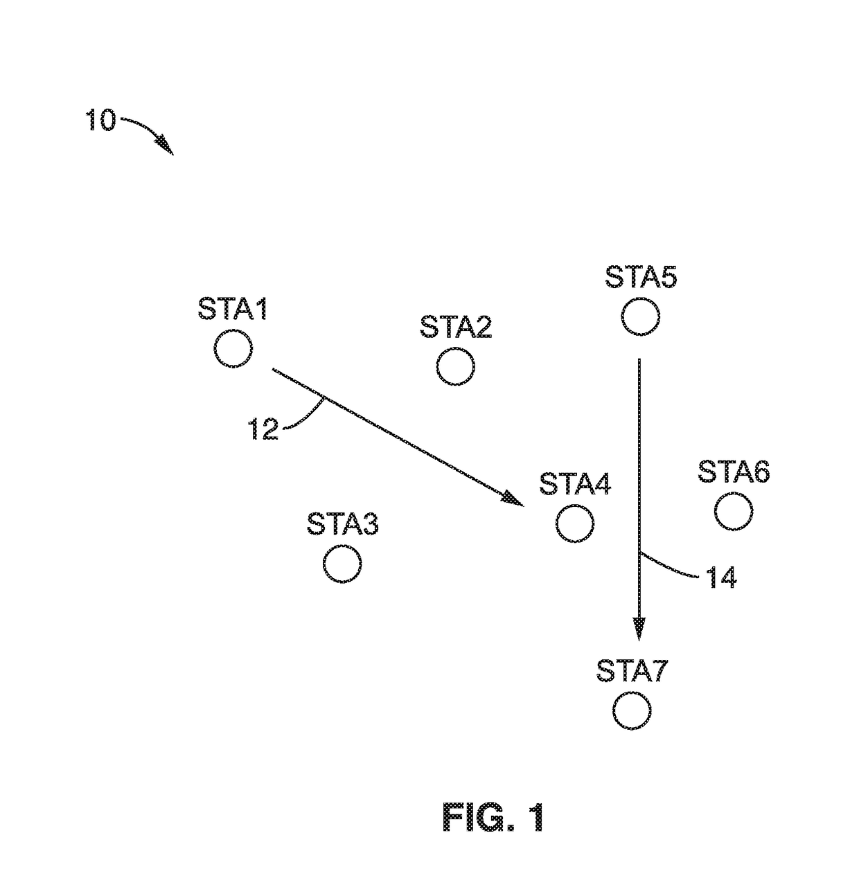
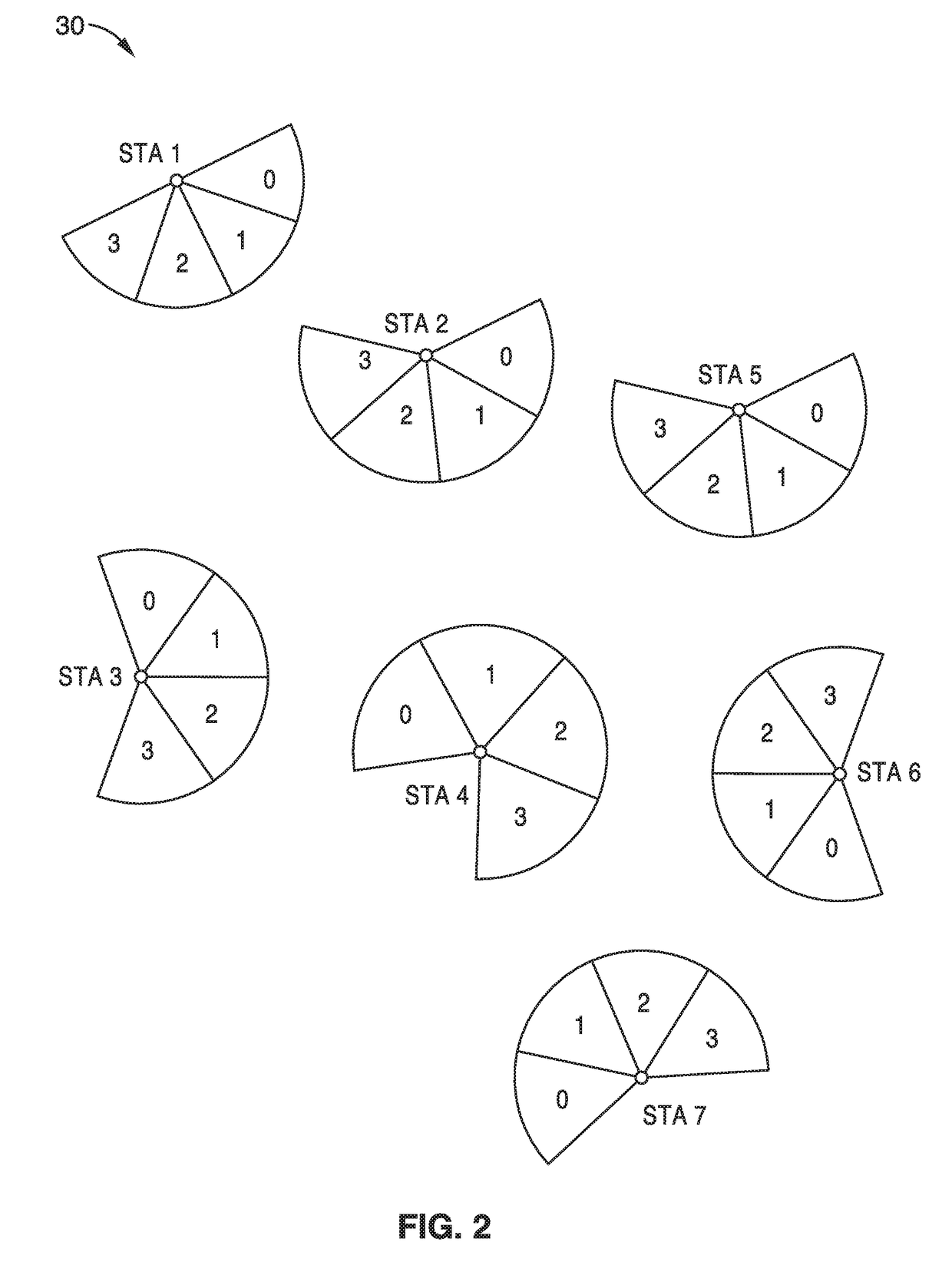
[0072]The existing 802.11ad protocol is a standard for 60 GHz PHY WLAN, and defines how to select antenna sectors for use by exchanging signals among 2 STAs (STA1 and STA2), assuming each STA has multiple antenna sectors and utilized the antenna sector which provides the highest link quality. The protocol defines sector sweep handshaking for initial sector learning, and beam refinement handshaking for maintenance of the beam forming. By completing these handshaking, STAs can learn which antenna sector should be used to secure the best link quality of the link.

[0073]However, 802.11ad does not consider limiting or mitigating interference to neighboring STAs, or mm-wave mesh network operations.

[0074]1.1 Routing Protocol Example (AODV)

[0075]Routing protocol is a set of rules to establish a communication path between an originating STA and a destination STA over multiple hops (intermediate STAs). AODV is a routing protocol which represent...


PUM


Abstract

Multiple-hop relayed directional beam formed wireless communication (mm-wave mesh network) method and apparatus which takes place at the PHY layer. Network capability is enhanced by improving routing protocols between neighboring STAs when communicating from an originating STA, through intermediate STAs, to a destination STA. The routing takes into consideration antenna sector selection to limit interference with neighboring STAs, and channel time utilization to increase throughput. Link metrics and channel times are established for optimizing routing and the determination of intermediate stations between an originating STA and a destination STA. The apparatus and method balances both end-end path link quality and interference impact.

Description

CROSS-REFERENCE TO RELATED APPLICATIONS[0001]This application is a continuation of U.S. patent application Ser. No. 15 / 618,577 filed on Jun. 9, 2017, incorporated herein by reference in its entirety.STATEMENT REGARDING FEDERALLY SPONSORED RESEARCH OR DEVELOPMENT[0002]Not ApplicableINCORPORATION-BY-REFERENCE OF COMPUTER PROGRAM APPENDIX[0003]Not ApplicableNOTICE OF MATERIAL SUBJECT TO COPYRIGHT PROTECTION[0004]A portion of the material in this patent document may be subject to copyright protection under the copyright laws of the United States and of other countries. The owner of the copyright rights has no objection to the facsimile reproduction by anyone of the patent document or the patent disclosure, as it appears in the United States Patent and Trademark Office publicly available file or records, but otherwise reserves all copyright rights whatsoever. The copyright owner does not hereby waive any of its rights to have this patent document maintained in secrecy, including without ...

Claims


Application Information

Patent Timeline
Patent Type & Authority Applications(United States)
IPC IPC(8): H04B7/0491H04L12/721H04B7/06
CPCH04W84/18H04B7/0695H04B7/088H04W40/06H04W40/22H04W40/24H04W40/12H04B7/0491H04L45/26H04B7/061
Inventor SAKODA, KAZUYUKI
Owner SONY CORP
Why Eureka
Try Eureka