Drive device for a bicycle driven by an electric motor

a technology of electric motors and drive devices, which is applied in the direction of axle suspensions, cycle frames, cycle equipments, etc., can solve the problems of chain being pulled back, unable to achieve the desired compression behavior conflict of objective, so as to achieve strong decompression of the rear linkage element, increase torque, and improve the effect of single pivo

Active Publication Date: 2019-01-31
QCS QUALITY CONSULT SERVICE GMBH
View PDF23 Cites 6 Cited by
  • Summary
  • Abstract
  • Description
  • Claims
  • Application Information

AI Technical Summary

Benefits of technology

[0059]The inventive drive device is provided for being used in e-bikes and, in particular, in full-suspension e-bikes. The inventive concept comprises providing a starting torque pitch support suitable for such e-bikes partly by means of chain pull and partly by means of specific rear linkage element kinematics. The present invention provides for realizing a rear linkage element behavior which is as neutral as possible, both when pedaling and when connecting the electric motor. In accordance with the invention, the transmission output is arranged to be offset to a drive, i.e. the pedal crank. In addition, the swing arm bearing is arranged to be close to the output. Close to the output means that the swing arm bearing is arranged closer to the output than to the drive. In other words, a radial distance between a center axis of the swing arm bearing and a center axis of the output shaft is smaller than a radial distance between the center axis of the swing arm bearing and a center axis of the first drive shaft. Due to this combination of an output offset to the drive and the arrangement of the swing arm bearing in direct proximity to the output, what results is a way of realizing a starting torque pitch support by means of chain pull and by means of the rear linkage element kinematics, i.e. by means of pivoting the rear linkage element relative to the main frame. This applies to both single pivots and multi pivots. Due to the radially offset output, the result is a relatively steep angle of the chain stay, which in turn results in stronger decompression of the rear linkage element. Due to these kinematic measures, the pitch caused by the additional torque of the electric motor can be supported. At the same time, arranging the output element close to the swing arm bearing provides for the starting torque pitch support needed when pedaling still to be influenceable by means of the chain pull, and keep being influenceable.
[0060]In accordance with an embodiment, the swing arm bearing may be positioned at the main frame such that the bicycle comprises a suspension oblique angle of 5° to 30°, advantageously 10° to 20° and even more advantageously of about 15° if the bike is subjected to a static load resulting in a negative spring deflection range between 10% and 35% of the total spring deflection. In other words, the bike comprises a suspension oblique angle in the indicated regions when being in the SAG. Providing a suspension oblique angle in the indicated regions results in a chassis-kinematics-conditioned starting torque pitch support with an increased torque and is of particular advantage in single pivots.
[0061]Another embodiment is of particular advantage for multi pivots where an instant center is designed to be an instantaneous center of rotation. In accordance with such an embodiment where the rear linkage element is configured to be a multi pivot having an instant center as an instantaneous center of rotation, the rear linkage element may be positioned at the main frame such that the bike comprises a suspension oblique angle of 5° to 30°, advantageously 10° to 20° and even more advantageously of about 15° if the bike is subjected to a static load resulting in a negative spring deflection between 10% and 35% of the total spring deflection. In other words, the bike comprises a suspension oblique angle in the indicated region when being in the SAG. Providing a suspension oblique angle in the indicated regions results in a chassis-kinematics-conditioned starting torque pitch support with an increased torque and is of particular advantage in multi pivots.
[0062]In accordance with an embodiment, the radial distance between the center axis of the first drive shaft and the center axis of the output shaft may be 200 mm to 30 mm and advantageously between 100 mm and 200 mm. Expressed differently, the distance between the pedal crank shaft and the output is 200 mm to 300 mm and advantageously 100 mm to 200 mm. Such an offset between drive and output has proven to be of particular advantage for providing a suitable starting torque pitch support.
[0063]In accordance with another embodiment, the radial distance between the center axis of the swing arm bearing and the center axis of the output shaft may be less than 200 mm, advantageously less than 100 mm and even more advantageously less than 50 mm. In other words, the offset or distance between the swing arm bearing and the output is less than 200 mm, advantageously less than 100 mm and even more advantageously less than 50 mm. The swing arm bearing is consequently arranged to be close to the output. This embodiment of course applies while keeping to the inventive concept relating to the distance between the radial distance between the center axis of the swing arm bearing and the center axis of the output shaft being smaller than the radial distance between the center axis of the swing arm bearing and the center axis of the first drive shaft. In accordance with this embodiment, the swing arm bearing may be arranged around the output with a radius of less than 200 mm, advantageously less than 100 mm and even more advantageously less than 50 mm. This allows a certain fine tuning or fine adjusting of the extent of compression or decompression of the rear linkage element, i.e. of the driving torque pitch support.

Problems solved by technology

When designing full-suspension bicycles, there is a conflict of objective between the so-called rocking of the rear linkage element and the so-called pedal kickback.
This compression behavior of the rear linkage element, however, is not desired since a high portion of the drive energy is lost by this.
However, too strong of a decompression behavior results in the chain being pulled back, counter-acting the crank movement, due to the decompressing rear linkage element.
This generates undesired compression of the rear linkage element when pedaling.
However, as has been mentioned before, there is the conflict of objective between the starting torque pitch support caused by chain pull and the so-called pedal kickback.
A deviation of the chain pull direction from the trajectory normal in turn will generate an undesired effect on the crank.
This means that nowadays there is a conflict of objective between anti-squat and pedal backlash.
However, in particular in riding situations where large a drive torque acts, like when starting, accelerating or riding uphill, the additional torque of the electric motor causes the rear linkage element of conventional bikes to decompress excessively.
On the one hand, this results in an unfamiliar and partly insecure riding behavior of the bike and, on the other hand, in a strong pedal backlash.
Consequently, when constructing the conventional bikes such that the starting torque pitch support works very well for drive by means of muscle power, when starting the electric motor, the rear linkage element will decompress too strongly.
If the rear linkage element of a conventional bike, however, is optimized to a starting torque pitch support for the torque of the electric motor, the rear linkage element would compress too strongly when pedaling.
Due to the radially offset output, the result is a relatively steep angle of the chain stay, which in turn results in stronger decompression of the rear linkage element.
This force results in decompression of the rear linkage element.

Method used


Image

  • Drive device for a bicycle driven by an electric motor
  • Drive device for a bicycle driven by an electric motor
  • Drive device for a bicycle driven by an electric motor

Examples


Embodiment Construction

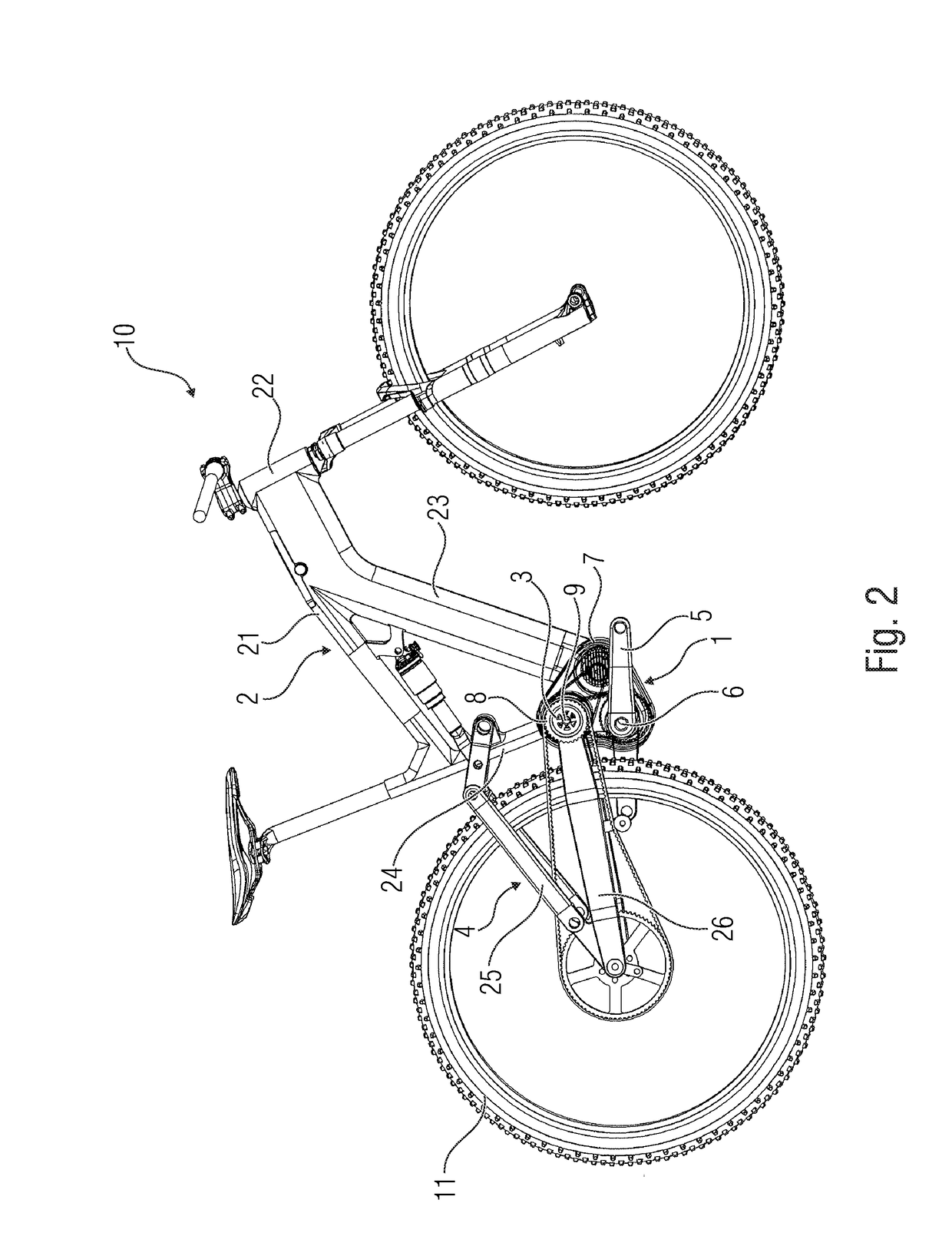
[0101]So-called e-bikes are generally meant by the term bicycles driven by an electric motor. Among these types of e-bikes which, for defining the present disclosure, fall under the term bicycle driven by an electric motor, are both bicycles driven by an electric motor which may be driven exclusively by the drive force of an electric motor, and bicycles supported by an electric motor which can switch in a drive force of an electric motor in support of the pedaling force.

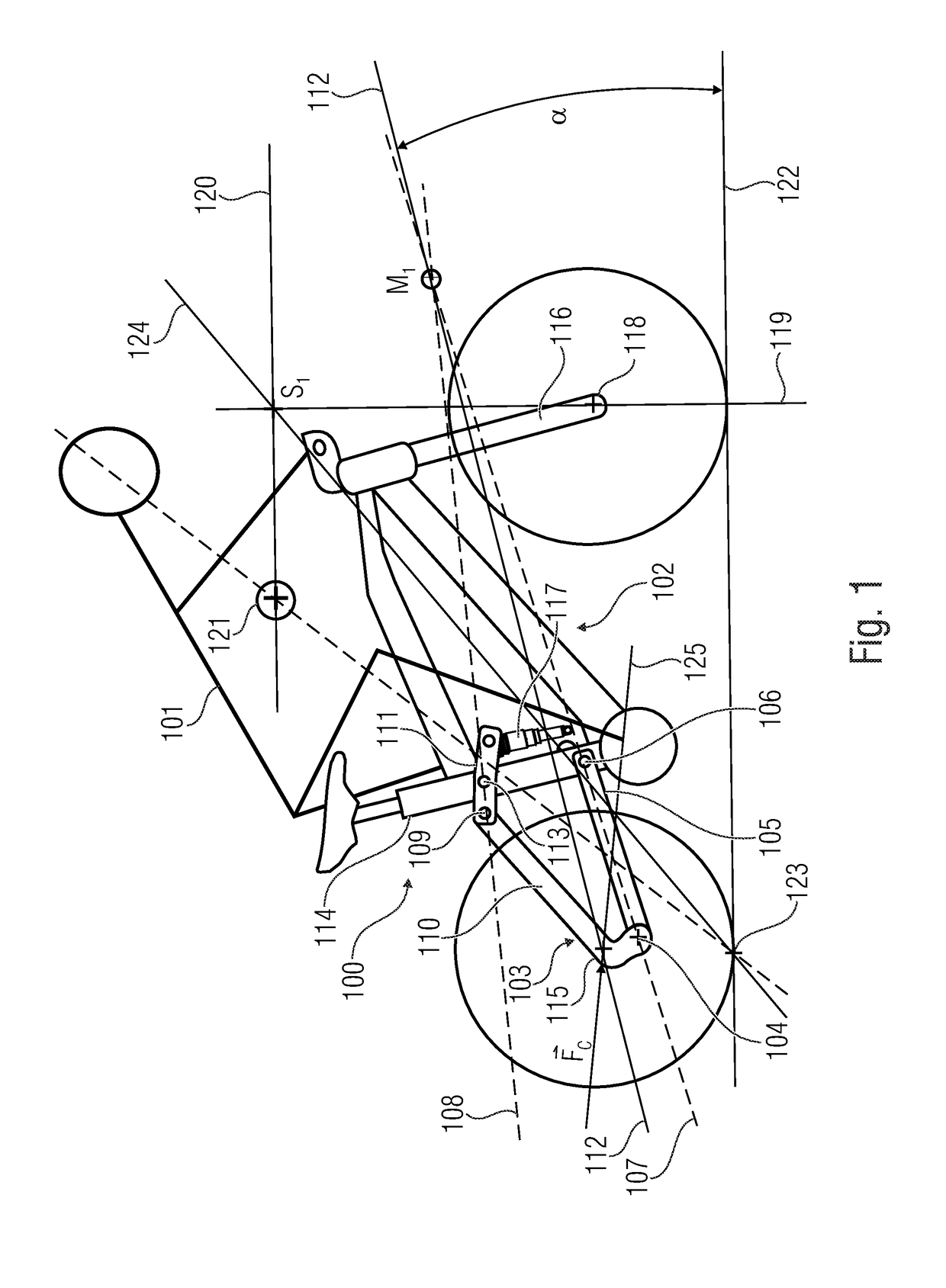
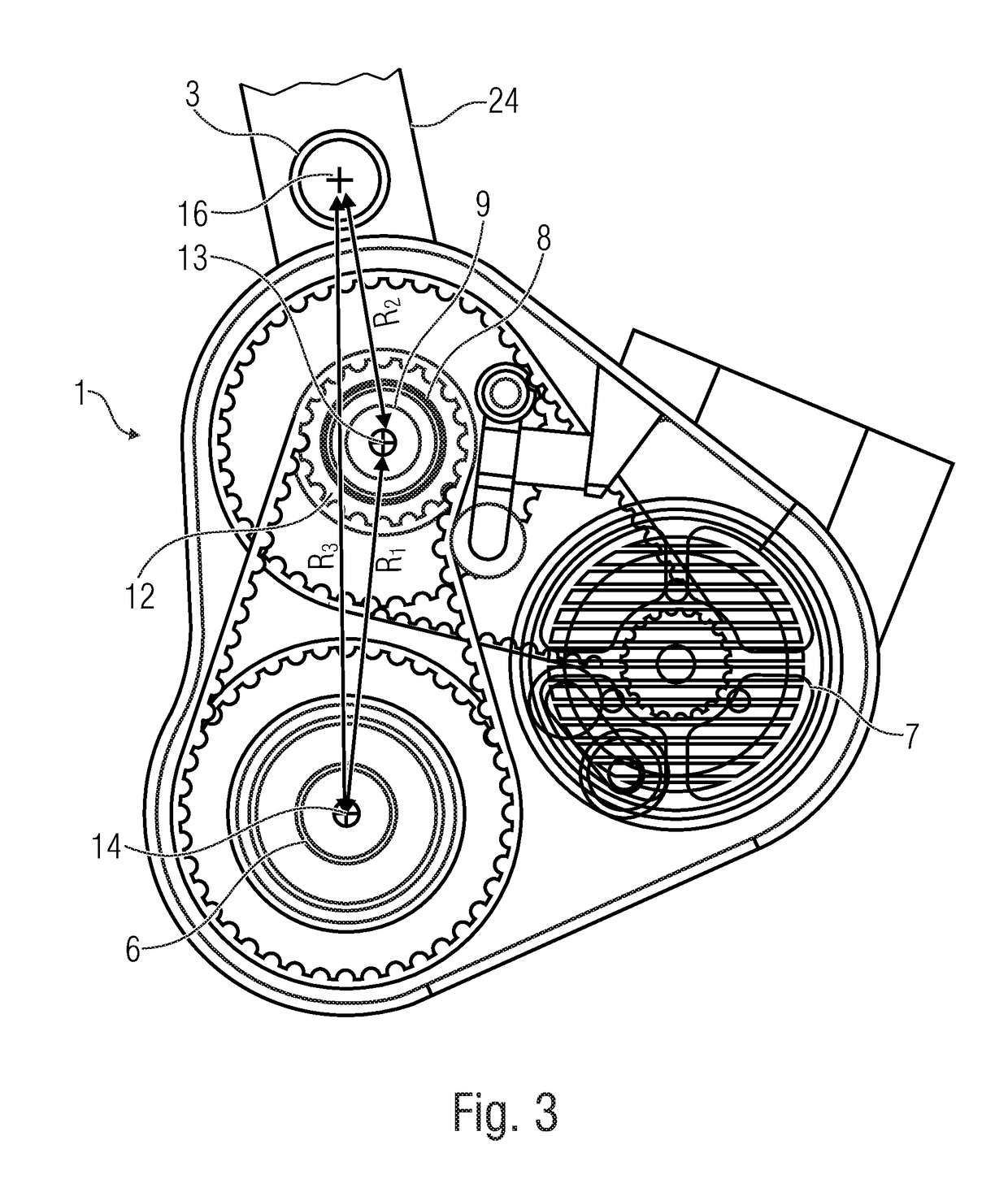
[0102]The shaft of the first drive, the shaft of the output element and an output shaft of the electric motor comprise a direction of extension along their longitudinal axis. A radial distance in the sense of the present disclosure relates to this longitudinal axis passing in the direction of extension of the respective shaft, which means that radial means a radial direction when starting from the longitudinal axis. The direction of extension of the longitudinal axis is usually roughly orthogonal to a vertical centra...


PUM


Abstract

What is disclosed is a drive device for a bicycle driven by an electric motor, having a main frame having a swing arm bearing, and a rear linkage element arranged at the swing arm bearing. The drive device has a pedal crank as a first drive for providing a first drive force, having a first drive shaft, a center electric motor as a second drive for providing a second drive force, and an output element having an output shaft, configured to receive the first and / or second drive forces and transfer same to the bicycle wheel to be driven. The center axis of the output shaft is radially distanced from the center axis of the first drive shaft and the output shaft is arranged relative to the swing arm bearing such that a radial distance between the center axis of the swing arm bearing and the center axis of the output shaft is smaller than a radial distance between the center axis of the swing arm bearing and the center axis of the first drive shaft.

Description

CROSS-REFERENCE TO RELATED APPLICATIONS[0001]This application is a continuation of co-pending International Application No. PCT / EP2017 / 057681, filed Mar. 31, 2017, which is incorporated herein by reference in its entirety, and additionally claims priority from German Application No. 10 2016 205 540.2, filed Apr. 4, 2016, which is also incorporate herein by reference in its entirety.BACKGROUND OF THE INVENTION[0002]The invention relates to a drive device comprising the features of claim 1 for a bicycle driven by an electric motor, to a usage in accordance with claim 12 of such a drive device in a bicycle driven by an electric motor, to a bicycle driven by an electric motor in accordance with claim 13 comprising such a drive device, and to a bicycle frame in accordance with claim 14 comprising such a drive device.[0003]Nowadays, bicycles are frequently used as means of transport and movement. There are different types of bicycles. Full-suspension bicycles are known, for example. These...

Claims


Application Information

Patent Timeline
Patent Type & Authority Applications(United States)
IPC IPC(8): B62K25/28B62M6/55B62M9/02B62K19/34B62K25/26
CPCB62K25/286B62M6/55B62M9/02B62K19/34B62K25/26B62K25/30
Inventor LAUER, SWEN
Owner QCS QUALITY CONSULT SERVICE GMBH
Why Eureka
Try Eureka