

Aircraft power setting trims for life extension
a technology for aircraft and trims, applied in the direction of machines/engines, mechanical equipment, transportation and packaging, etc., can solve the problems of stacked list of uncertainties, newer engines use up turbine life, etc., and achieve the effect of reducing the amount of thrus
- Summary
- Abstract
- Description
- Claims
- Application Information
AI Technical Summary
Benefits of technology
Problems solved by technology
Method used
Image

Examples
Embodiment Construction
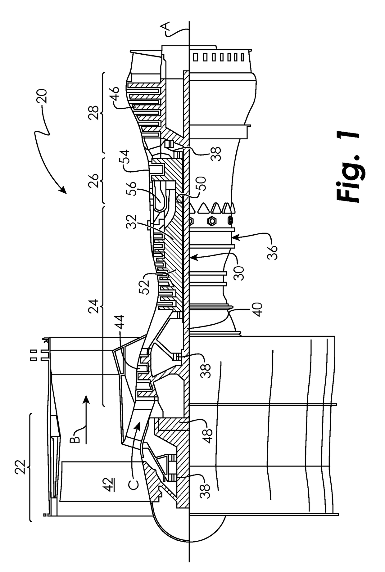
[0003]In one aspect, a method of controlling thrust for a gas turbine engine of an aircraft is provided. The method includes determining a fan speed required for minimum thrust to achieve an aircraft operation. The method also includes determining an excess amount of thrust generated by the gas turbine engine. The method also includes reducing the amount of thrust generated by the gas turbine engine.
[0004]In a further embodiment of the above, determining a fan speed includes determining a fan speed based on a gross weight of the aircraft.
[0005]In a further embodiment of any of the above, determining a fan speed includes determining a fan speed based on a length of a runway upon which the aircraft is located.
[0006]In a further embodiment of any of the above, determining a fan speed includes determining a fan speed based on an ambient temperature.
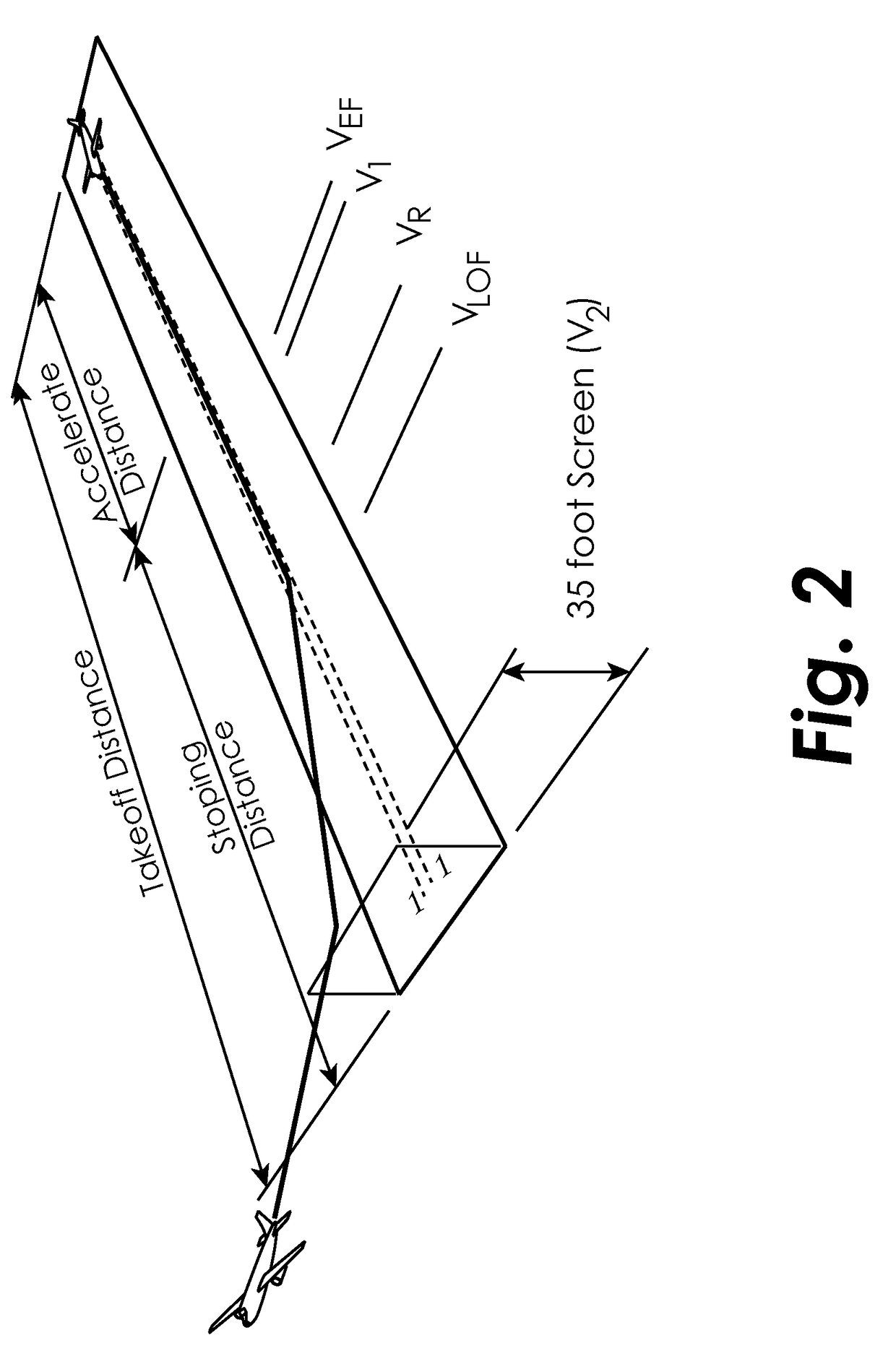
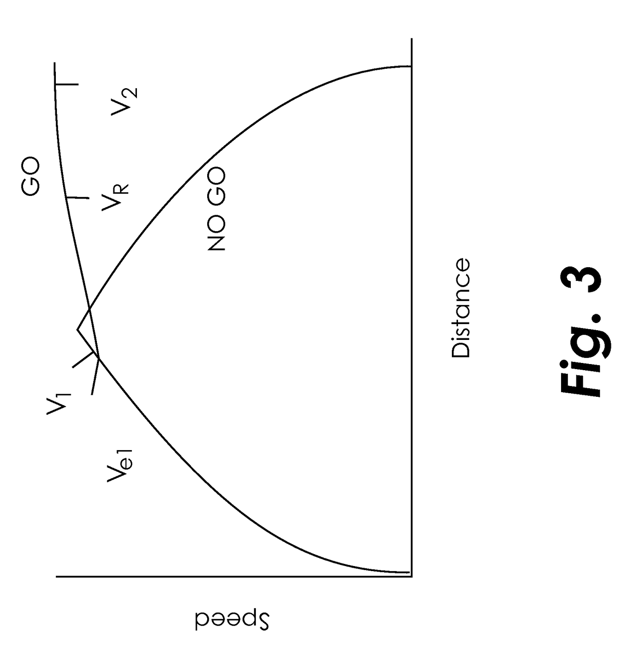
[0007]In a further embodiment of any of the above, determining an excess amount of thrust includes determining a speed of the aircraft.
[0008...
PUM
 Abstract
Description
Claims
Application Information