Spar cap and production method

a production method and technology of spar caps, applied in the field of spar caps, can solve the problems of increasing the mechanical stress of individual components, the risk of being struck, and the risk of lightning striking the supporting structure of the wind power installation, so as to reduce the thickness of the spar cap along the longitudinal direction

Active Publication Date: 2019-01-31
WOBBEN PROPERTIES GMBH
View PDF5 Cites 0 Cited by
  • Summary
  • Abstract
  • Description
  • Claims
  • Application Information

AI Technical Summary

Benefits of technology

[0071]One preferred refinement of the production method explained above provides that the number of tiers of the first fiber composite material is reduced toward the second end, wherein the reduction in tiers is performed either continuously or at defined spacings. The number of tiers of the first fiber composite material that are disposed on top of one another is substantially reduced herein such that two layers, composed of tiers of the first fiber composite material

Problems solved by technology

Wind power installations, by way of the construction height thereof and the exposed locations are more at risk of being struck by lightning in the case of thunderstorms.
In the case of a lightning strike there is the risk of the lightning striking the supporting structure of the wind power installation.
The increasing size of the wind power installations in turn leads to ever higher mechanical stresses of the individual components, inter alia of the components in the rotor blades.
However, this increasing thickness

Method used


Image

  • Spar cap and production method
  • Spar cap and production method
  • Spar cap and production method

Examples


Embodiment Construction

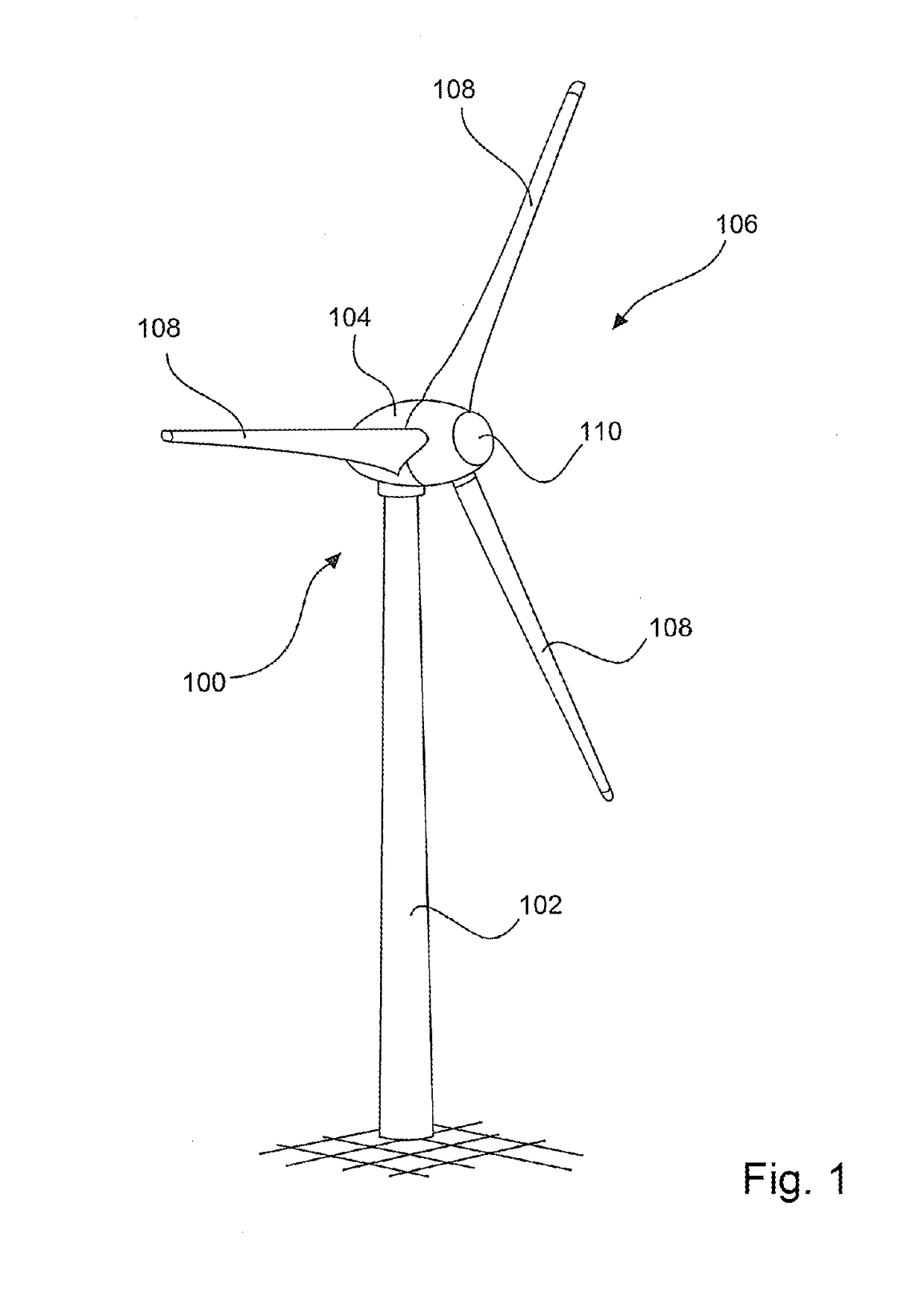
[0085]FIG. 1 shows a schematic illustration of a wind power installation. FIG. 1 shows a wind power installation 100 having a tower 102 and a nacelle 104. A rotor 106 having three rotor blades 108 and a spinner 110 is disposed on the nacelle 104. The rotor 106 in operation is set in rotary motion by the wind and on account thereof drives a generator in the nacelle 104.

[0086]Spar caps 200 according to the invention are used in particular for the longitudinal reinforcement of the rotor blades 108. For this purpose, at least one spar cap 200, preferably two spar caps 200, are disposed in the interior of the rotor blade 108 and are preferably fastened to a side facing the interior of the rotor blade 108.

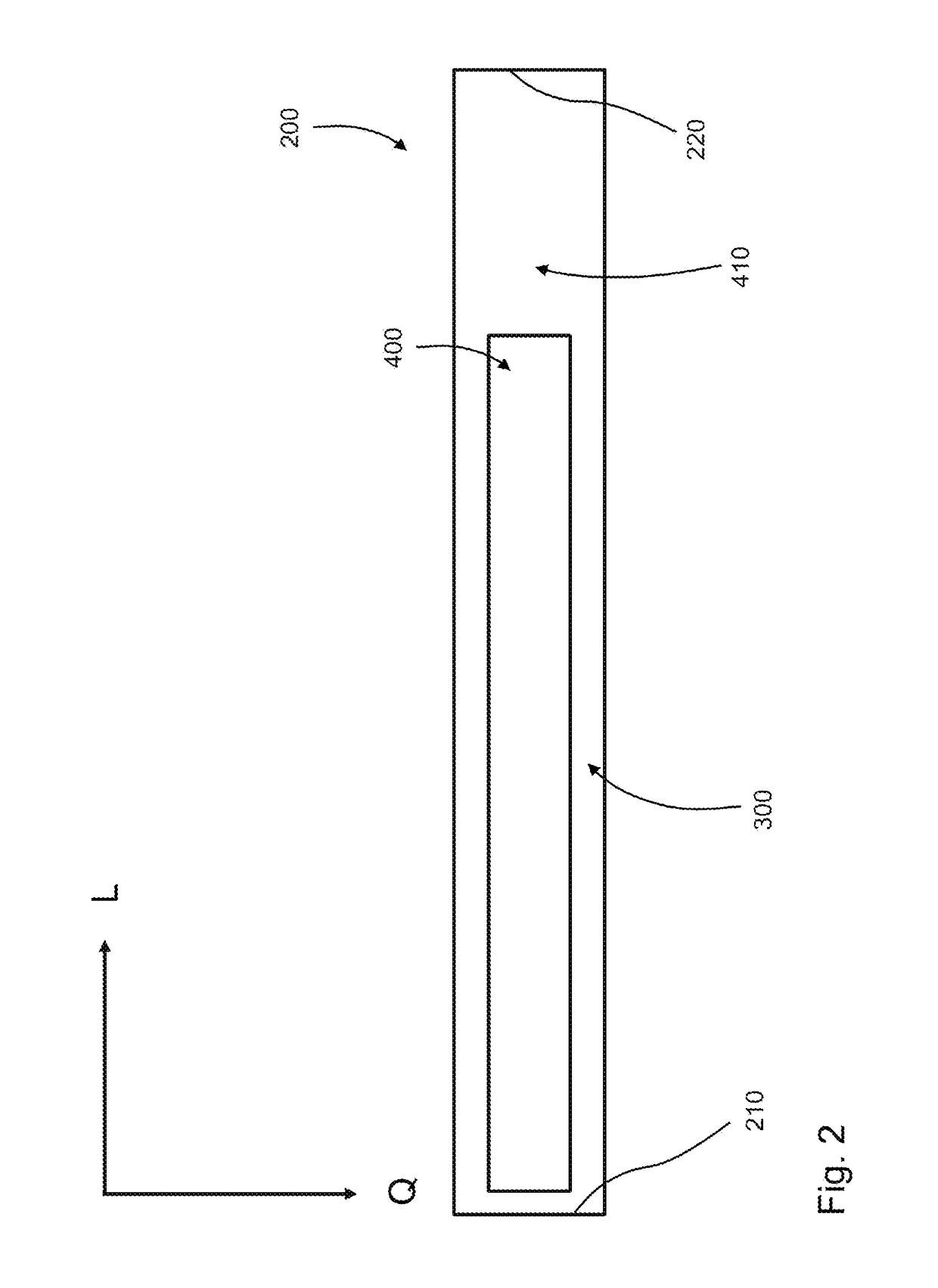
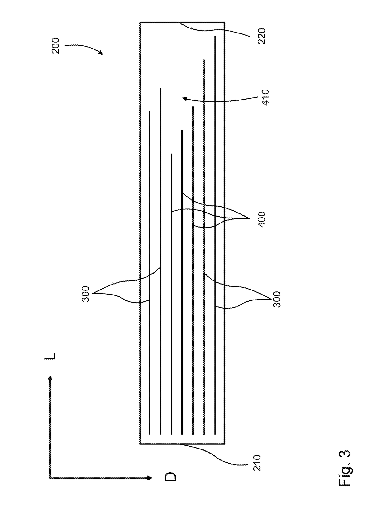
[0087]FIG. 2 shows a schematic cross-sectional view in the direction of a longitudinal extent L and transverse extent Q of a spar cap 200. The spar cap extends longitudinally along the longitudinal extent L thereof from a first end 210 to a second end 220. The first end 210 preferably re...


PUM

PropertyMeasurementUnit
Electrical conductivityaaaaaaaaaa

Abstract

A spar cap for a rotor blade of a wind power installation, having a longitudinal extent from a first end to a second end, a transverse extent orthogonal to the longitudinal extent, and a thickness orthogonal to the longitudinal extent and to the transverse extent. A method for producing a spar cap as mentioned at the outset. The spar cap has a longitudinal extent from a first end to a second end, a transverse extent orthogonal to the longitudinal extent, and a thickness orthogonal to the longitudinal extent and to the transverse extent, at least two tiers of a first fiber composite material, and at least one tier of a second fiber composite material, wherein the first fiber composite material has a matrix material and/or fibers which is/are different from that/those of the second fiber composite material, the second fiber composite material is disposed in a portion adjacent to the second end, in the direction of the thickness between the at least two tiers of the first fiber composite material, and the at least one tier of the second fiber composite material terminates ahead of the second end.

Description

BACKGROUNDTechnical Field[0001]The invention relates to a spar cap for a rotor blade of a wind power installation. The invention furthermore relates to a rotor blade of a wind power installation, having a spar cap as mentioned at the outset. The invention moreover relates to a wind power installation having a tower, a nacelle, and a rotor, characterized in that the rotor has at least one rotor blade having a spar cap as mentioned at the outset. The invention moreover relates to a method for producing a spar cap as mentioned at the outset.Description of the Related Art[0002]Spar caps of the type mentioned at the outset are, for example, components of rotor blades, preferably rotor blades of wind power installations, or of aircraft wings which are in particular configured so as to be reinforced in the longitudinal direction. A reinforcement of this type serves in particular for absorbing forces which run along a longitudinal extent, wherein the aforementioned longitudinal extent in th...

Claims


Application Information

Patent Timeline
IPC IPC(8): F03D1/06B29C70/08B29C70/34B29C70/88B32B5/26B32B7/02F03D80/30
CPCF03D1/0675B29C70/08B29C70/34B29C70/885B32B5/26B32B7/02F03D80/30B29L2031/085B32B2603/00F05B2230/50F05B2280/2001F05B2280/2006F05B2280/6003F05B2280/6015B32B5/022B32B5/024B32B9/005B32B9/04B32B9/041B32B9/045B32B13/02B32B13/04B32B13/06B32B13/12B32B15/08B32B15/14B32B15/20B32B18/00B32B27/08B32B3/30B32B2250/03B32B2250/44B32B2260/023B32B2260/04B32B2260/044B32B2260/046B32B2262/0253B32B2262/0269B32B2262/0276B32B2262/065B32B2262/10B32B2262/101B32B2262/103B32B2262/105B32B2262/106B32B2307/202B32B2307/546C04B2237/38Y02E10/72Y02P70/50B32B7/022F03D1/06
Inventor RUBNER, FLORIANVINKE, DANIEL
Owner WOBBEN PROPERTIES GMBH
Why Eureka
Try Eureka