Ventilating device

a technology of temperature/humidity sensor and ventilation device, which is applied in ventilation systems, lighting and heating apparatus, heating types, etc., can solve the problems of not being able to perform work or operation conveniently before maintenance is actually performed, and achieve the effect of improving the accuracy of temperature and humidity sensed, relatively large resistance of the first air path, and relatively more turbulen

Active Publication Date: 2019-01-31
PANASONIC ECOLOGY SYSTEMS GUANGDONG CO LTD
View PDF1 Cites 4 Cited by
  • Summary
  • Abstract
  • Description
  • Claims
  • Application Information

AI Technical Summary

Benefits of technology

[0023]When the motor is disposed at the first air suction port side, and the distance from the first air suction port to the top surface is greater than the distance from the second air suction port to the bottom surface, the amount of air entering the air blower from the first air suction port is less than that entering the air blower from the second air suction port, that is, the air volume flowing through the first air path is less than the air volume flowing through the second air path. In addition, since the motor is disposed in the first air path, the resistance of the first air path is relatively larger and the turbulence is relatively more. Since the air volume flowing through the second air path is more and the turbulence is relatively less, the sensor storage unit is disposed in the second air path, so that the humidity and the temperature may be correctly sensed, thereby improving the accuracy of the temperature and humidity sensed by the sensor storage unit.
[0024](5) The first end of the sensor storage unit is disposed on the wall of the circuit board box, and the second end extends outwards from the circuit board box, and the air entrance port is disposed at the second end. With the above structure, the air entering the frame from the air inlet flows directly to the air entrance port opposite to the air inlet. The humidity and temperature of the air entering the frame may be more quickly and accurately detected by the sensor provided in the sensor storage unit. In addition, the air entrance port is provided on the second end of the sensor storage unit extending outwards from the circuit board box. In this way, the second end is closer to the air blower or the air inlet side, and more air enters the sensor storage unit. Therefore, although the circuit board box is provided in a space with a small air flow, the sensor may accurately detect the humidity and temperature of the air entering the frame, ensuring the accuracy of the temperature and humidity sensed by the sensor.

Problems solved by technology

That is, work or operation may not be performed conveniently before the maintenance is actually performed.

Method used


Image

  • Ventilating device
  • Ventilating device
  • Ventilating device

Examples


Embodiment Construction

[0058]The present disclosure provides a ventilating device that can use less components, facilitate assembly and disassembly of components, and improve maintenance convenience by reasonably setting the positions of the circuit board box and the sensor storage unit.

[0059]To make the purpose, technical solutions, and advantages of the present application clearer, the following further describes the present disclosure in detail with reference to specific embodiments and the accompanying drawings.

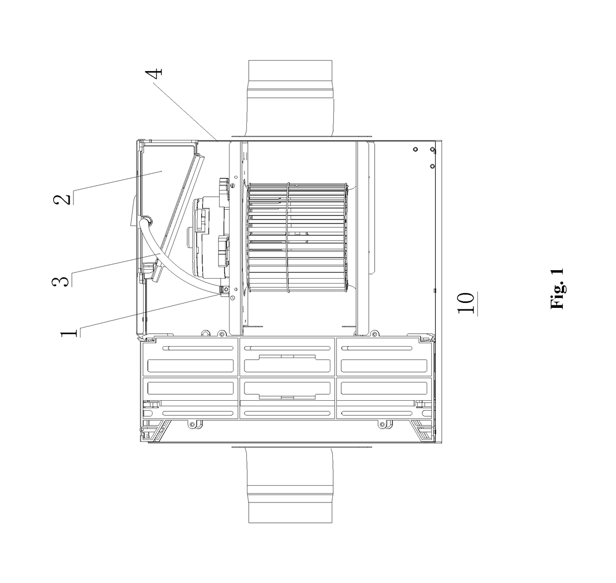
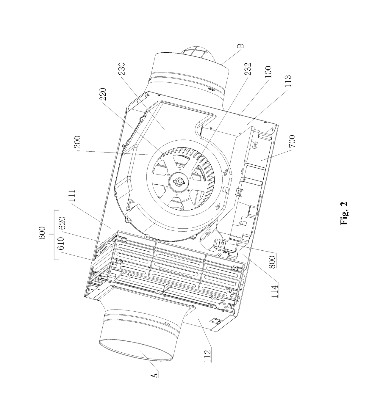
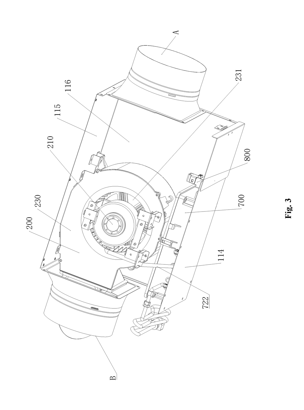
[0060]In an exemplary embodiment of the present disclosure, a ventilating device is provided. FIG. 2 is a schematic structural view of a ventilating device with a bottom surface removed according to an embodiment of the present disclosure. FIG. 3 is a schematic diagram of the ventilating device shown in FIG. 2 viewed from the top surface side with a top surface and a filter unit removed. As shown in FIG. 2, the ventilating device in this embodiment includes a frame 100, an air blower 200, a sen...


PUM


Abstract

The present disclosure provides a ventilating device. the ventilating device includes: a frame formed with an external profile; an air inlet provided in the frame; an air outlet provided in the frame; an air blower for guiding air from the air inlet to the air outlet; a control circuit board connected to the air blower and configured to control operation of the air blower; and a circuit board box for housing the control circuit board; wherein the circuit board box includes an integrally formed sensor storage unit for storing a sensor connected to the control circuit board and capable of sensing humidity or temperature. The ventilating device of the present disclosure may use less components, facilitate assembly and disassembly of components, and improve convenience in maintenance.

Description

CROSS REFERENCE TO RELATED APPLICATIONS[0001]This application claims priority to Chinese Patent Application No. 201720926752.X, filed Jul. 27, 2017, the contents of such application being incorporated by reference herein.BACKGROUND OF THE INVENTIONField of the Invention[0002]The present disclosure relates to a ventilating device and more particularly to a ventilating device with a temperature / humidity sensor.Description of the Related Art[0003]FIG. 1 is a schematic diagram of a connection between a sensor and a circuit board box in a ventilating device in a related art. As shown in FIG. 1, in the ventilating device 10 of the related art, in order to more accurately detect temperature or humidity of air entering from an air inlet, a sensor 1 that senses the temperature or humidity is provided at a place proximate to the air inlet. However, since the sensor 1 needs to be connected with the circuit board so as to be controlled and be powered by the same, in the related art, a circuit b...

Claims


Application Information

Patent Timeline
Patent Type & Authority Applications(United States)
IPC IPC(8): F24F11/89F24F7/007
CPCF24F11/89F24F7/007F24F2013/205F24F2110/10F24F2110/20
Inventor YANG, DECONGPANG, GUOFENGGONG, WENTIANCHEN, RUNXIN
Owner PANASONIC ECOLOGY SYSTEMS GUANGDONG CO LTD
Why Eureka
Try Eureka