Route analysis device, route analysis method, and computer-readable recording medium
- Summary
- Abstract
- Description
- Claims
- Application Information
AI Technical Summary
Benefits of technology
Problems solved by technology
Method used
Image

Examples
first embodiment
[0031]Hereinafter, a route analysis device, a route analysis method, and a program of a first embodiment of the present invention will be described with reference to FIGS. 1 to 8.
[0032]Device Configuration
[0033]First, the schematic configuration of the route analysis device of the first embodiment will be described. FIG. 1 is a block diagram showing the schematic configuration of the route analysis device according to the first embodiment of the present invention.
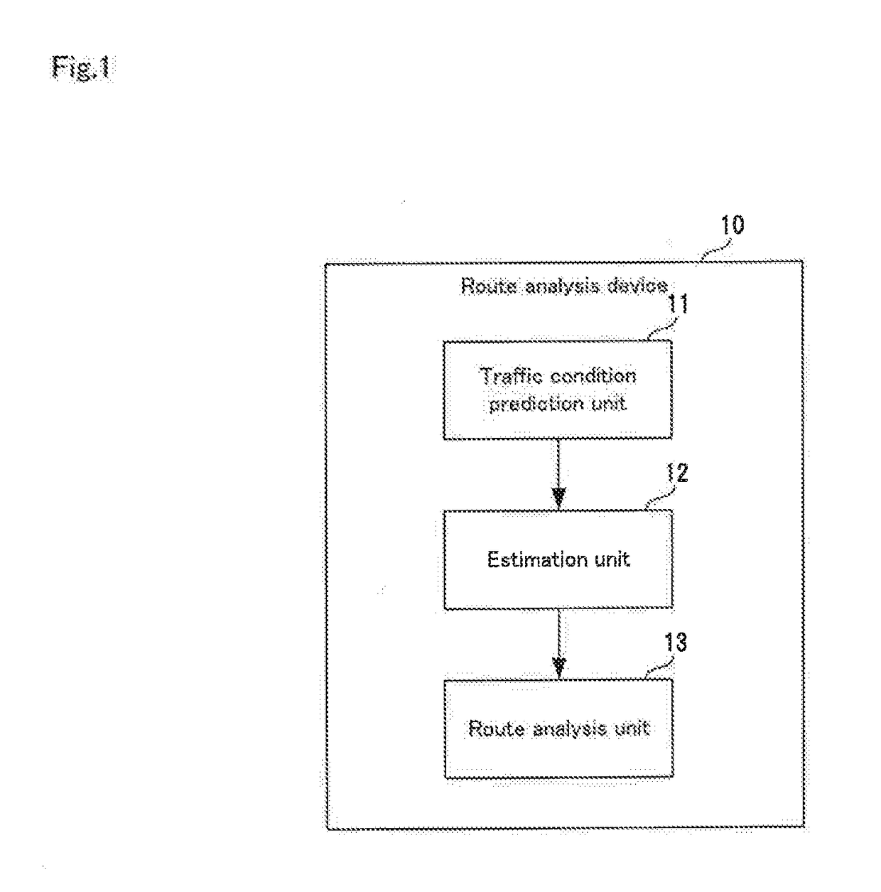
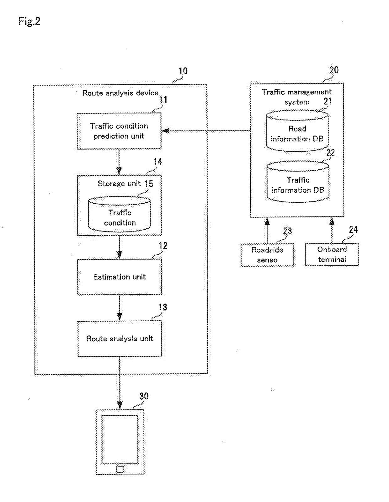
[0034]A route analysis device 10 of the first embodiment shown in FIG. 1 is a device for analyzing routes from a departure location to a destination. As shown in FIG. 1, the route analysis device 10 includes a traffic condition prediction unit 11, an estimation unit 12, and a route analysis unit 13.
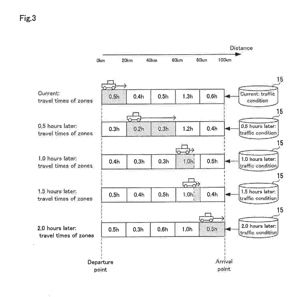
[0035]The traffic condition prediction unit 11 predicts, for each of multiple future times, the traffic condition in each of multiple zones that exist from the departure location to the destination.
[0036]The estimation unit 12 se...
second embodiment
[0070]Next, a route analysis device, a route analysis method, and a program of a second embodiment of the present invention will be described.
[0071]First, the route analysis device of the second embodiment is configured similarly to the route analysis device 10 of the first embodiment shown in FIGS. 1 and 2. Furthermore, in the second embodiment as well, the route analysis device operates in accordance with steps A1 to A4 shown in FIG. 5.
[0072]It should be noted that the route analysis device of the second embodiment is different from the route analysis device of the first embodiment with respect to only operations performed by the traffic condition prediction unit 11 and the estimation unit 12. Specifically, in the second embodiment, the traffic condition prediction unit 11 acquires a speed in each zone as the traffic condition for each future time. Also, after selecting one of the traffic conditions, for each of the zones, the estimation unit 12 obtains a short-of-arrival distance...
application examples
[0090]In the present invention, the first and second embodiments described above are applicable to not only car navigation systems, but also to other applications. One example of another application is a communication network. Specifically, with the present invention, a communication network topology is subjected to time expansion based on prediction values of arrival times for packets between communication devices (routers, etc.). By calculating a lowest cost route in the expanded time topology, it is possible to obtain a network route that achieves the smallest communication delay.
[0091]In this case, the traffic condition prediction unit functions as a network condition prediction unit and predicts network conditions. Also, the estimation unit estimates transfer speeds or arrival times for packets in the network. Also, according to this aspect, it is possible to avoid the case where the amount of communication between devices increases in a certain region, particularly, the case w...
PUM
 Abstract
Description
Claims
Application Information
 - R&D
- Intellectual Property
- Life Sciences
- Materials
- Tech Scout
- Unparalleled Data Quality
- Higher Quality Content
- 60% Fewer Hallucinations
Browse by: Latest US Patents, China's latest patents, Technical Efficacy Thesaurus, Application Domain, Technology Topic, Popular Technical Reports.
© 2025 PatSnap. All rights reserved.Legal|Privacy policy|Modern Slavery Act Transparency Statement|Sitemap|About US| Contact US: help@patsnap.com