Optical image capturing system

Active Publication Date: 2019-01-31
ABILITY OPTO ELECTRONICS TECH
View PDF7 Cites 5 Cited by
  • Summary
  • Abstract
  • Description
  • Claims
  • Application Information

AI Technical Summary

Benefits of technology

[0048]Besides, the eighth lens may have negative refractive power, and the image side of the eighth lens may be a concave surface. Hereby, this configuration is beneficial to shorten the back focal length of the optical image capturing system in order to keep the op

Problems solved by technology

Nevertheless, the ICR elements occupy a significant amount of space and are expensive, whi

Method used


Image

  • Optical image capturing system
  • Optical image capturing system
  • Optical image capturing system

Examples


Example

The First Embodiment

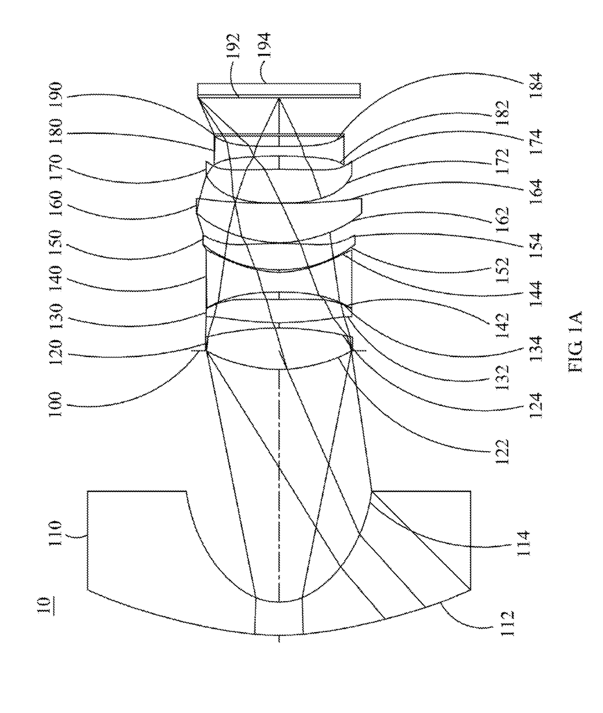
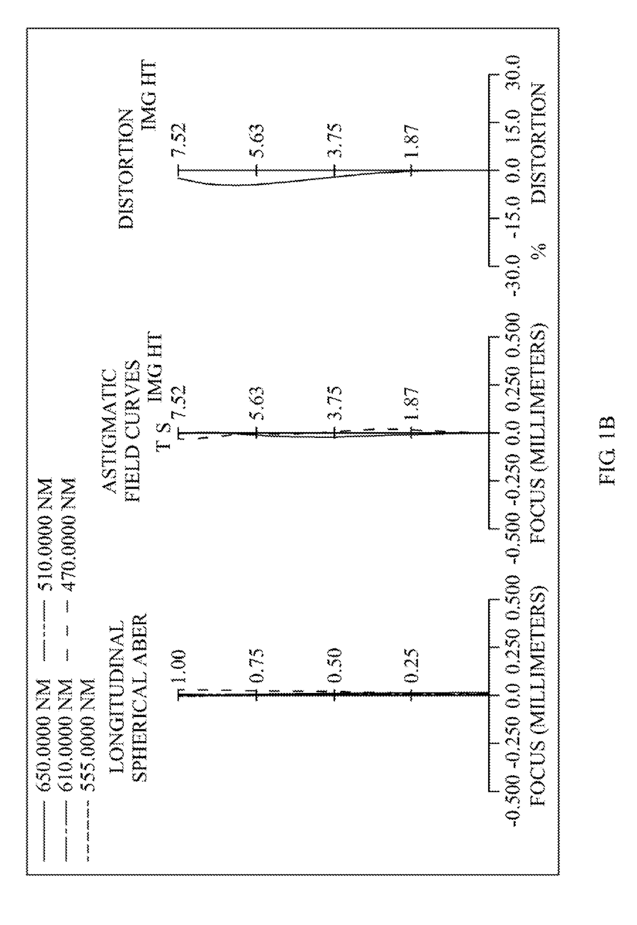
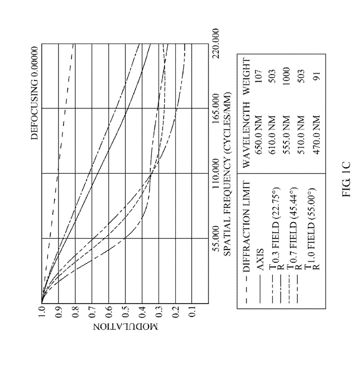
[0109]Please refer to FIG. 1A and FIG. 1B, wherein FIG. 1A is a schematic view of the optical image capturing system according to the first embodiment of the present invention and FIG. 1B shows the longitudinal spherical aberration curves, astigmatic field curves, and optical distortion curve of the optical image capturing system in the order from left to right according to the first embodiment of the present invention. FIG. 1C is a characteristic diagram of modulation transfer of the visible light spectrum according to the first embodiment of the present disclosure. FIG. 1D is a diagram illustrating the through focus MTF values for the visible light spectrum at central field of view, 0.3 field of view and 0.7 field of view according to the first embodiment of the present disclosure. FIG. 1E is a diagram illustrating the through focus MTF values for the infrared light spectrum at central field of view, 0.3 field of view and 0.7 field of view according to the firs...

Example

Second Embodiment

[0173]Please refer to FIG. 2A and FIG. 2B, wherein FIG. 2A is a schematic view of the optical image capturing system according to the second embodiment of the present invention and FIG. 2B shows the longitudinal spherical aberration curves, astigmatic field curves, and optical distortion curve of the optical image capturing system in the order from left to right according to the second embodiment of the present invention. FIG. 2C is a characteristic diagram of modulation transfer of the visible light spectrum according to the second embodiment of the present disclosure. FIG. 2D is a diagram illustrating the through focus MTF values for the visible light spectrum at central field of view, 0.3 field of view and 0.7 field of view according to the first embodiment of the present disclosure. FIG. 2E is a diagram illustrating the through focus MTF values for the infrared light spectrum at central field of view, 0.3 field of view and 0.7 field of view according to the seco...

Example

Third Embodiment

[0188]Please refer to FIG. 3A and FIG. 3B, wherein FIG. 3A is a schematic view of the optical image capturing system according to the third embodiment of the present invention and FIG. 3B shows the longitudinal spherical aberration curves, astigmatic field curves, and optical distortion curve of the optical image capturing system in the order from left to right according to the third embodiment of the present invention. FIG. 3C is a characteristic diagram of modulation transfer of the visible light spectrum according to the third embodiment of the present disclosure. FIG. 3D is a diagram illustrating the through focus MTF values for the visible light spectrum at central field of view, 0.3 field of view and 0.7 field of view according to the first embodiment of the present disclosure. FIG. 3E is a diagram illustrating the through focus MTF values for the infrared light spectrum at central field of view, 0.3 field of view and 0.7 field of view according to the third em...


PUM


Abstract

The invention discloses an eight-piece optical lens for capturing image and an eight-piece optical module for capturing image. In order from an object side to an image side, the optical lens along the optical axis comprises a first lens with refractive power; a second lens with refractive power; a third lens with refractive power; a fourth lens with refractive power; a fifth lens with refractive power; a sixth lens with refractive power; a seventh lens with refractive power; and an eighth lens with refractive power; and at least one of the image side and object side of each of the eight lenses can be aspheric. The optical lens can increase aperture value and improve the imagining quality for use in compact cameras.

Description

CROSS-REFERENCE TO RELATED APPLICATION[0001]This application claims priority from Taiwan Patent Application No. 106125352, filed on Jul. 27, 2017, in the Taiwan Intellectual Property Office, the disclosure of which is hereby incorporated by reference in its entirety for all purposes.BACKGROUND OF THE INVENTION1. Field of the Invention[0002]The present invention relates to an optical image capturing system, and more particularly is about a minimized optical image capturing system which can be applied to electronic products.2. Description of the Related Art[0003]In recent years, as the popularization of portable electronic devices with camera functionalities, it has elevated the demand for optical system. The photosensitive element of ordinary optical system is commonly selected from charge coupled device (CCD) or complementary metal-oxide semiconductor sensor (CMOS Sensor). Besides, as the advancement in semiconductor devices manufacturing technology, the pixel size of the photosensi...

Claims


Application Information

Patent Timeline
IPC IPC(8): G02B9/64G02B7/04H04N5/232G02B27/00
CPCG02B9/64G02B7/04H04N5/23212G02B27/0037G02B13/0045G02B13/18G02B13/008G02B13/04G02B13/146H04N23/67
Inventor CHANG, YEONG-MINGLAI, CHIEN-HSUNTANG, NAI-YUAN
Owner ABILITY OPTO ELECTRONICS TECH
Why Eureka
Try Eureka