Optical image capturing system

Active Publication Date: 2021-03-04
ABILITY OPTO ELECTRONICS TECH
View PDF1 Cites 0 Cited by
  • Summary
  • Abstract
  • Description
  • Claims
  • Application Information

AI Technical Summary

Benefits of technology

[0043]When a relationship of |f2|+|f3|>|f1|+|f4| is met, at least one of the second to the third lenses may have a weak positive refractive power or a weak negative refractive power. The aforementioned weak refractive power indicates that an absolute value of the focal length of a specific lens is greater than 10. When at least one of the second lens to the third lens has the weak positive refractive power, the positive refractive power of the first lens may be shared, so as to prevent unnecessary aberration f

Problems solved by technology

Nevertheless, the ICR is bulky in size and expensive, so as to be disadvantageous

Method used


Image

  • Optical image capturing system
  • Optical image capturing system
  • Optical image capturing system

Examples


Example

First Embodiment

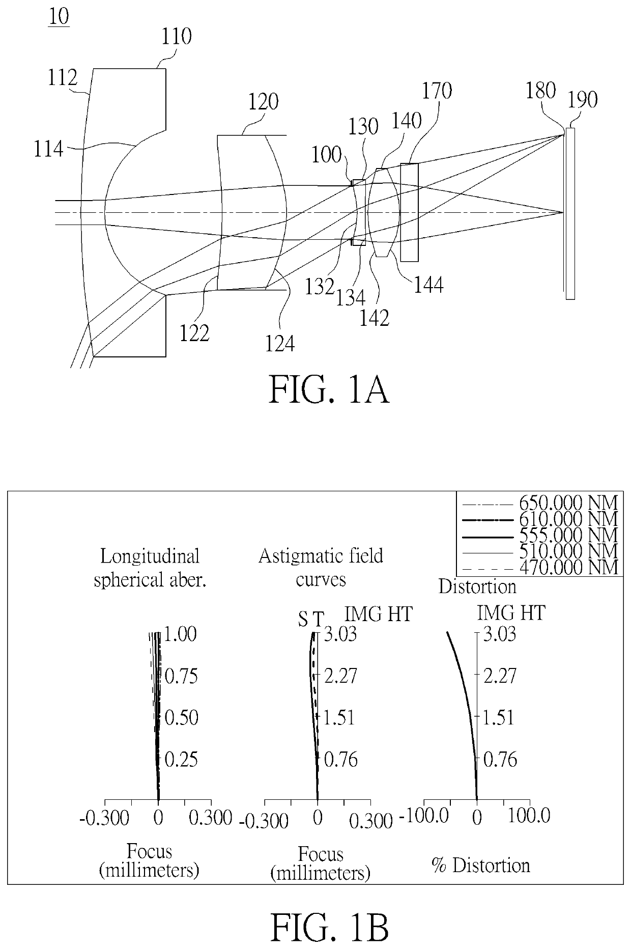
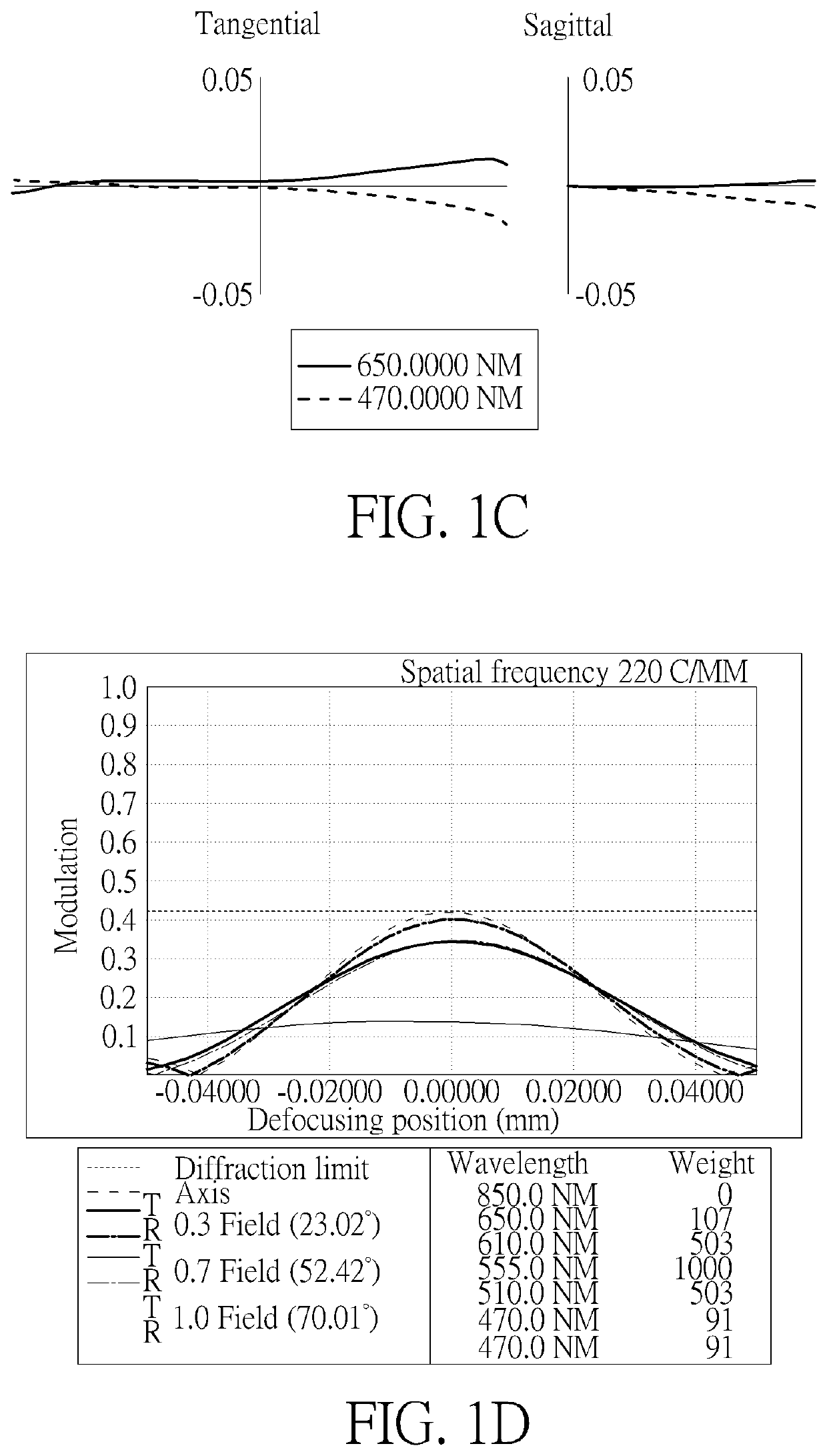
[0113]Please refer to FIGS. 1A and 1B, wherein FIG. 1A is a schematic view of the optical image capturing system according to the first embodiment of the present disclosure; FIG. 1B is a curve diagram illustrating the spherical aberration, astigmatism and optical distortion of the optical image capturing system in sequence from left to right according to the first embodiment of the present disclosure; FIG. 1C is a transverse aberration diagram of the longest operation wavelength and the shortest operation wavelength for tangential fan and sagittal fan, of which the longest operation wavelength and the shortest operation wavelength pass through the edge of the aperture at the position of 0.7 field of view on the image plane according to the first embodiment of the present disclosure; FIG. 1D is a diagram illustrating the through-focus MTF values for the visible light spectrum at the central field of view, 0.3 field of view and 0.7 field of view of the first embodiment...

Example

Second Embodiment

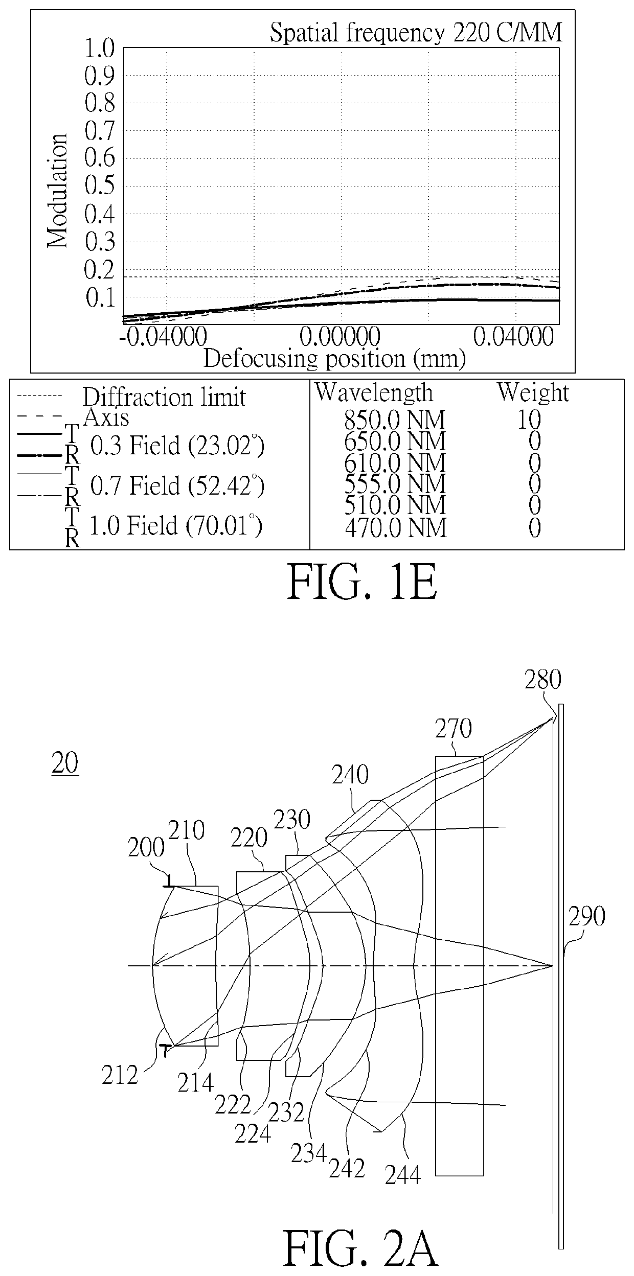
[0158]Please refer to FIGS. 2A and 2B, wherein FIG. 2A is a schematic view of the optical image capturing system according to the second embodiment of the present disclosure. FIG. 2B is a curve diagram illustrating the spherical aberration, astigmatism and optical distortion of the optical image capturing system in sequence from left to right according to the second embodiment of the present disclosure. FIG. 2C is a transverse aberration diagram of the longest operation wavelength and the shortest operation wavelength for tangential fan and sagittal fan, of which the longest operation wavelength and the shortest operation wavelength pass through an edge of aperture at the position of 0.7 field of view on the image plane according to the second embodiment of the present disclosure. FIG. 2D is a diagram illustrating the through-focus MTF values for the visible light spectrum at the central field of view, 0.3 field of view and 0.7 field of view of the second embodiment...

Example

Third Embodiment

[0169]Please refer to FIGS. 3A and 3B, wherein FIG. 3A is a schematic view of the optical image capturing system according to the third embodiment of the present disclosure. FIG. 3B is a curve diagram illustrating the spherical aberration, astigmatism and optical distortion of the optical image capturing system in sequence from left to right according to the third embodiment of the present disclosure. FIG. 3C is a transverse aberration diagram of the longest operation wavelength and the shortest operation wavelength for tangential fan and sagittal fan, of which the longest operation wavelength and the shortest operation wavelength pass through an edge of aperture at the position of 0.7 field of view on the image plane according to the third embodiment of the present disclosure. FIG. 3D is a diagram illustrating the through-focus MTF values for the visible light spectrum at the central field of view, 0.3 field of view and 0.7 field of view of the third embodiment of t...


PUM


Abstract

The invention discloses a four-piece optical lens for capturing image and a four-piece optical module for capturing image. From an object side to an image side, the optical lenses along the optical axis comprises a first lens with refractive power, a second lens with refractive power, a third lens with refractive power, and a fourth lens with refractive power; and at least one of an image-side surface and object-side surface of each of the four lens elements are aspheric. The optical lens can increase aperture value and improve the image quality for use in compact cameras.

Description

BACKGROUND OF THE INVENTION1. Field of the Invention[0001]The present disclosure relates to an optical image capturing system, and more particularly to a compact optical image capturing system which can be applied to electronic products.2. Description of the Prior Art[0002]In recent years, with the rise of portable electronic devices having camera functionalities, the demand for an optical image capturing system gradually increased. The image sensing devices of ordinary optical systems is commonly selected from charge coupled devices (CCD) or complementary metal-oxide semiconductor sensors (CMOS sensors). As advanced semiconductor manufacturing technology enables the miniaturization of pixel sizes of the image sensing device, the development of optical image capturing systems has been directed towards developing systems with high pixel counts, thereby increasing the demand on image quality.[0003]Traditional optical image capturing systems of a portable electronic device mainly compr...

Claims


Application Information

Patent Timeline
IPC IPC(8): G02B13/00G02B9/34G02B3/04
CPCG02B13/004G02B3/04G02B9/34
Inventor CHANG, YEONG-MINGLAI, CHIEN-HSUNLIU, YAO-WEI
Owner ABILITY OPTO ELECTRONICS TECH
Why Eureka
Try Eureka