Multi-mirror heliostat

Inactive Publication Date: 2015-07-02
MITAKA KOHKI
View PDF11 Cites 3 Cited by
  • Summary
  • Abstract
  • Description
  • Claims
  • Application Information

AI Technical Summary

Benefits of technology

[0007]To solve the problem of the related art, the present invention provides a multi-mi

Problems solved by technology

As the size of the mirror assembly increases, the aberration becomes larger.
Due to this, the

Method used


Image

  • Multi-mirror heliostat
  • Multi-mirror heliostat
  • Multi-mirror heliostat

Examples


Example

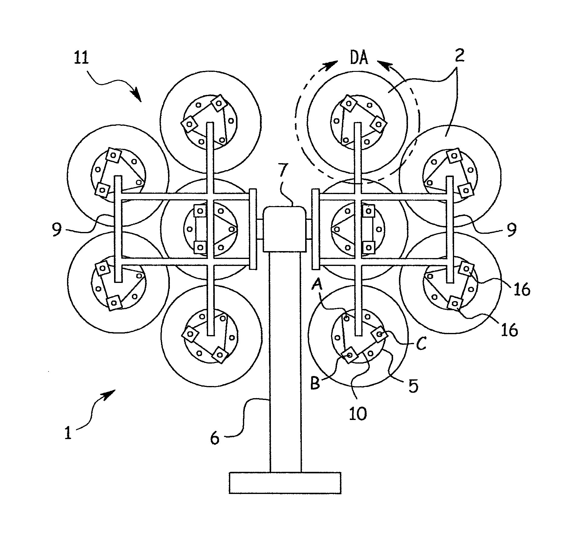
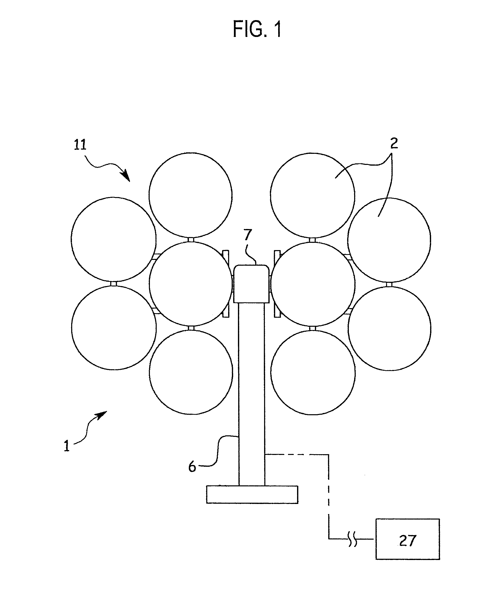
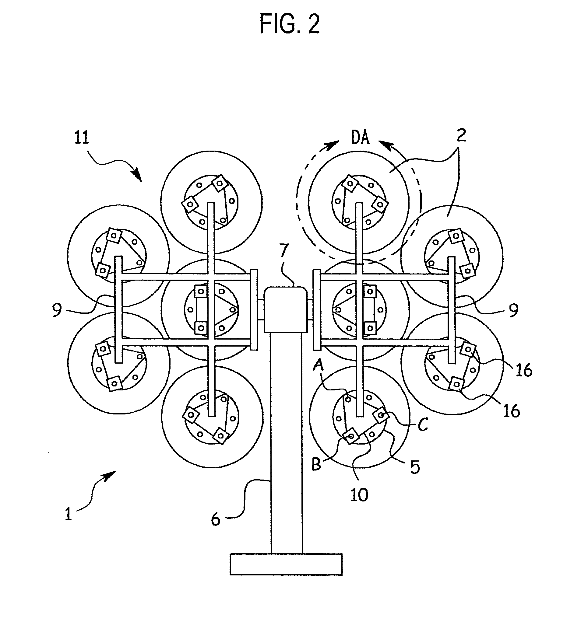
[0023]A multi-mirror heliostat according to an embodiment of the present invention will be explained with reference to FIGS. 1 to 14.

[0024]The multi-mirror heliostat 1 has ten mirrors 2. A number of such heliostats 1 are arranged in a field around a tower (not illustrated) having a target at the top thereof. Each of the heliostats 1 reflects sunlight onto the target of the tower.

[0025]Each of the mirrors 2 of the heliostat 1 is circular having a diameter of 50 centimeters. A reflection surface of the mirror 2 is a concave (or spherical) mirror whose curvature is dependent on a substantial focal length. As illustrated in FIG. 8, the mirror 2 is bonded to a base 3 made of aluminum alloy and the back of the base 3 is supported with a spacer 4 that is fixed to a disk 5 made of metal.

[0026]The heliostat 1 has a support post 6 that is fixed to the ground. Arranged at the top of the support post 6 is a drive 7 that is turnable in a horizontal direction. From the drive 7, a rotary shaft 8 h...


PUM


Abstract

A heliostat includes mirrors. Each mirror is supported with a frame at three points including a fulcrum and movable points. The movable points are provided with electric extendable units, respectively. The electric extendable units are separately controlled to change distances between the mirror and the frame at the movable points, thereby correcting an aberration of the mirror and always directing reflected light from the mirror toward a predetermined position.

Description

BACKGROUND OF THE INVENTION[0001]1. Field of the Invention[0002]The present invention relates to a multi-mirror heliostat.[0003]2. Description of Related Art[0004]A heliostat is an apparatus having a mirror that is turned to track the sun and continuously reflect sunlight onto a given spot. One type of the heliostat employs and turns a single large mirror. Another type is a multi-mirror heliostat that employs a plurality of mirrors to form a mirror assembly and turns the mirror assembly like a single large mirror. The multi-mirror heliostat is advantageous because each mirror may involve a smaller distortion and the mirror assembly is adjustable to accurately reflect and concentrate light onto a given spot.[0005]The multi-mirror heliostat supports the mirrors with a frame and separately adjusts the angle of each mirror so that sunlight made incident to the mirror assembly in an optical axis direction of the mirror assembly may be reflected by each mirror onto a target position. The ...

Claims


Application Information

Patent Timeline
IPC IPC(8): G02B7/183F24S50/20F24S23/71
CPCG02B7/183G02B7/1821F24S23/70F24S23/71F24S23/72F24S30/45F24S2023/874F24S2050/25Y02E10/47Y02E10/40
Inventor NAKAMURA, KATSUSHIGE
Owner MITAKA KOHKI
Why Eureka
Try Eureka