Optical image capturing system

Active Publication Date: 2021-08-05
ABILITY OPTO ELECTRONICS TECH
0 Cites 0 Cited by

AI-Extracted Technical Summary

Problems solved by technology

However, pixel counts of portable devices continue to increase, and end users require large apertures to fulfill functionalities such as micro filming and night filming.
Thus, optical image capturing systems in prior arts cannot me...

Method used

[0058]In addition, in the optical image capturing system of the disclosure, at least one aperture may be configured depending on requirements so as to reduce stray light and improve image quality.
[0059]In the optical image capturing system of the disclosure, the aperture may be configured as a front-set aperture or middle-set aperture, wherein the front-set aperture is disposed between a photographed object and the first lens, and the middle-set aperture is disposed between the first lens and the image plane. If the aperture is the front-set aperture, a longer distance between the exit pupil and the image plane of the optical image capturing system may be provided, such that more optical elements may be accommodated in the optical image capturing system, and an efficiency of the image sensing device in receiving images may be improved. If the aperture is the middle-set aperture, an angle of field of view (FOV) of the optical image capturing system may be expanded, such that the optical image capturing system has the same advantage as wide-angle cameras. A distance from the aforementioned apertures to the image plane is denoted as InS, which meets the following conditions: 0.2≤InS/HOS≤1.1. Hence, the optical image capturing system may simultaneously be miniaturized while equipped with wide-angle features.
[0063]A distance between the first lens and the second lens on the optical axis is denoted as IN12. The following condition is met: 0≤IN12/f≤5.0. Hence, chromatic aberration of the lens may be mitigated, such that performance thereof is improved.
[0064]A distance between the fourth lens and the fifth lens on the optical axis is denoted as IN45. The following condition is met: IN45/f≤5.0. Hence, chromatic aberration of the lens may be mitigated, such that performance thereof is improved.
[0065]A central thicknesses of the first lens and the second lens on the optical axis are denoted as TP1 and TP2, respectively, which meets the following condition: 0.1≤(TP1+IN12)/TP2≤50.0. Hence, a sensitivity formed via the optical image capturing system may be easier to control, and performance of the optical image capturing system may be improved.
[0068]In the optical image capturing system of the present disclosure, a perpendicular distance between a critical point C51 on the object-side surface of the fifth lens and the optical axis is denoted as HVT51. A perpendicular distance to the optical axis between a critical point C52 on the image-side surface of the fifth lens and the optical axis is denoted as HVT52. A horizontal shift distance in parallel with the optical axis between an intersection of the object-side surface of the fifth lens on the optical axis and the critical point C51 is denoted as SGC51. A horizontal shift distance in parallel with the optical axis between an intersection of the image-side surface of the fifth lens on the optical axis and the critical point C52 is denoted as SGC52. The following conditions are satisfied: 0 mm≤HVT51≤3 mm; 0 mm52≤6 mm; 0≤HVT51/HVT52; 0 mm≤|SGC51|≤0.5 mm; 0 mm<|SGC52|≤2 mm; and 0≤|SGC52|/(SGC52|+TP5)≤0.9. Hence, an off-axis FOV aberration may be effectively corrected.
[0077]In one embodiment of the optical image capturing system of the present disclosure, a chromatic aberration of the optical image capturing system may be easier to correct via alternately arranging lenses with a large Abbe number and a small Abbe number.
[0080]In the optical image capturing system provided by the present disclosure, a material of lens may be glass or plastic. If a plastic material is adopted, a manufacture cost as well as a weight of the lens may be reduced effectively. If a glass material is adopted, a heat effect may be controlled, and a design space for configuring the lenses with their respective refractive powers of the optical image capturing system may also be increased. Additionally, the object-side surface and the image-side surface of the first to the fifth lens in the optical image capturing system may be aspheric surfaces, which provide more controlled variables, such that the number of lenses used may be less than that the number of lenses used when traditional glass lenses are selected; in addition, the aberration may be mitigated as well. Hence, the total height of the optical image capturing system may be reduced effectively.
[0086]Electronic products utilizing the optical image capturing system of the present disclosure may comprise a light admitting opening. The aforementioned light admitting opening may be a front-set aperture for an electronic product, and the light admitting opening is for limiting an optical path of incident light. The light admitting opening has a diameter denoted as DDH. The optical image capturing system of the present disclosure may further comprise at least one reflective element such as a prism or a reflective mirror d...

Benefits of technology

[0030]When a relationship of |f2|+|f3|+|f4|>|f1|+|f5| is met, at least one of the second to the fourth lens may have a weak positive refractive power or a weak negative refractive power. The aforementioned weak refractive power indicates that an absolute value of the focal length of a specific lens is greater than 10. When at least one of the second lens to the forth lens has the weak positive refractive power, the positive refractive power of the first lens may be shared, so as to prevent unnecessary aberration from appearing too early. On the contrary, when at least one of the second le...

Abstract

The invention discloses a five-piece optical lens for capturing image and a five-piece optical module for capturing image. In order from an object side to an image side, the optical lens along the optical axis comprises a first lens with refractive power; a second lens with refractive power; a third lens with refractive power; a fourth lens with refractive power; a fifth lens with refractive power; and at least one of the image-side surface and object-side surface of each of the five lens elements is aspheric. The optical lens can increase aperture value and improve the imaging quality for use in compact cameras.

Application Domain

Television system detailsColor television details +1

Technology Topic

OphthalmologyOptical axis +4

Image

  • Optical image capturing system
  • Optical image capturing system
  • Optical image capturing system

Examples

  • Experimental program(6)

Example

First Embodiment
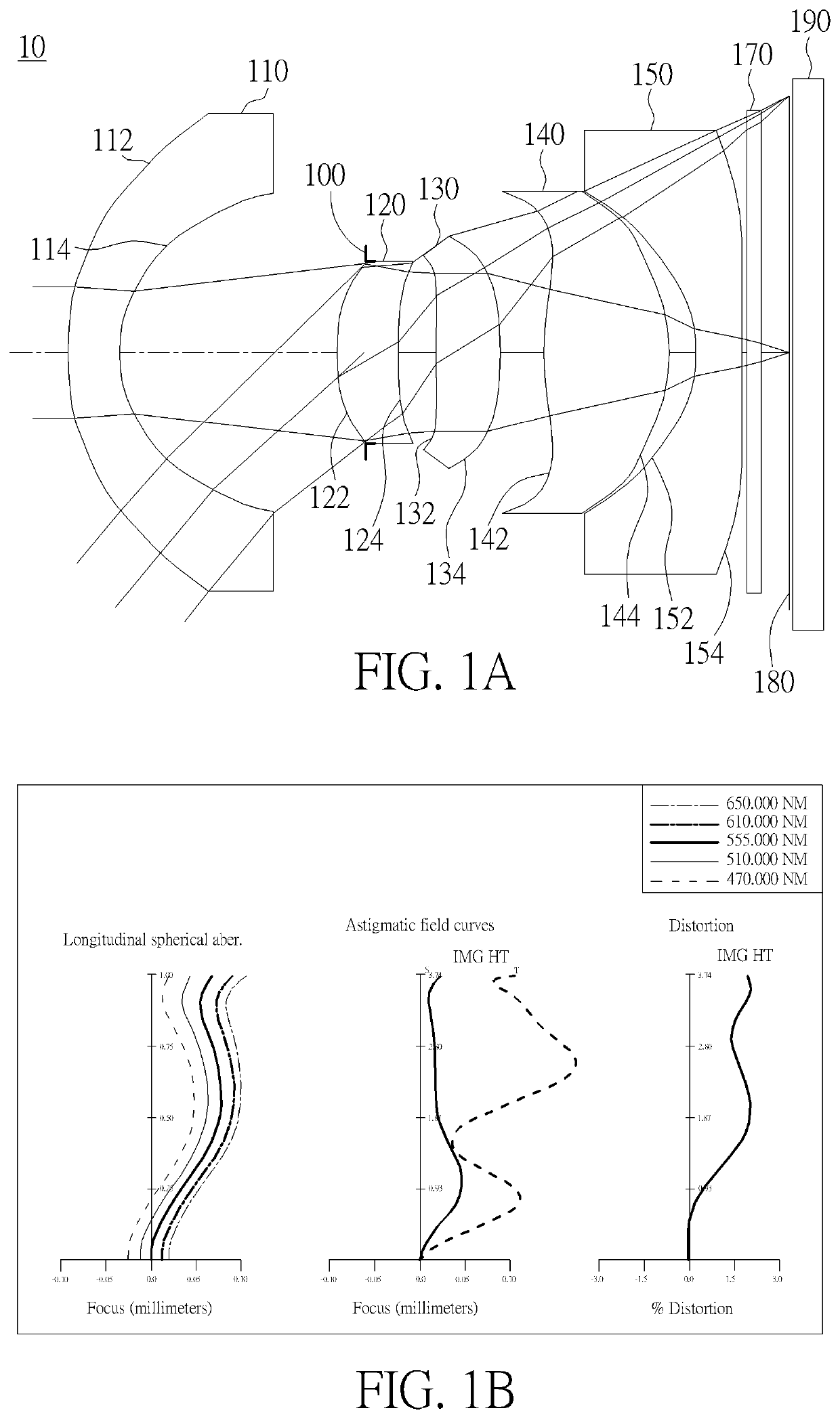
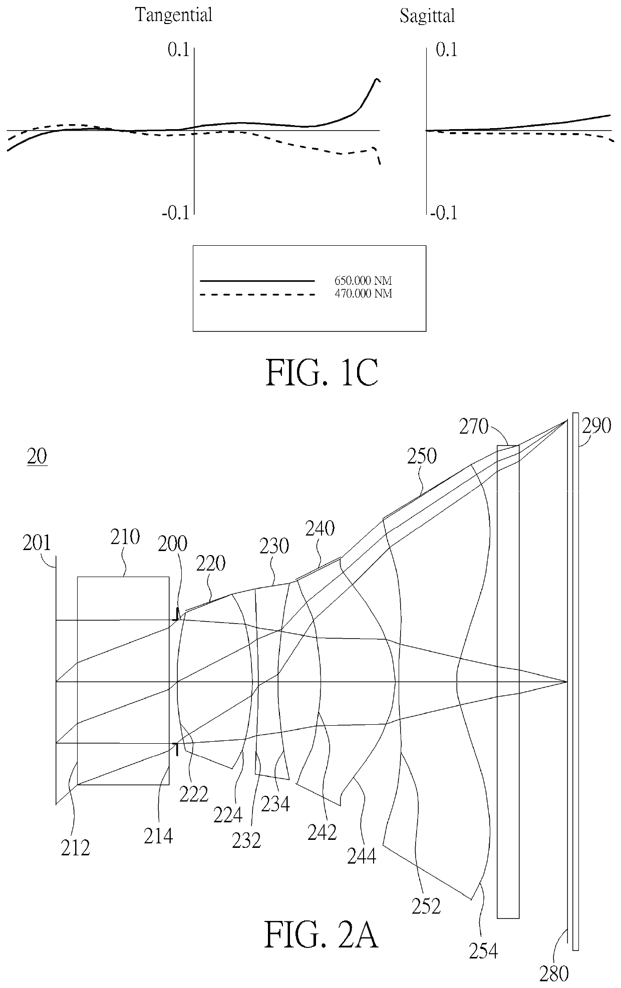
[0088]Please refer to FIGS. 1A and 1B, wherein FIG. 1A is a schematic view of the optical image capturing system according to the first embodiment of the present disclosure; FIG. 1B is a curve diagram illustrating the spherical aberration, astigmatism and optical distortion of the optical image capturing system in sequence from left to right according to the first embodiment of the present disclosure; FIG. 1C is a transverse aberration diagram of the longest operation wavelength and the shortest operation wavelength for tangential fan and sagittal fan, of which the longest operation wavelength and the shortest operation wavelength pass through the edge of the aperture at the position of 0.7 field of view on the image plane according to the first embodiment of the present disclosure. As shown in FIG. 1A, it may be seen that, in the order from the object side to the image side, the optical image capturing system includes a first lens 110, an aperture 100, a second lens 120, a third lens 130, a fourth lens 140, a fifth lens 150, an infrared filter 170, an image plane 180, and an image sensing device 190.
[0089]First lens 110 has negative refractive power and is made of plastic materials. The first lens 110 has a convex object-side surface 112 and a concave image-side surface 114, wherein both of the surfaces are aspheric, and the object-side surface 112 thereof has an inflection point. The outline curve length of the maximum effective half diameter of the object-side surface of the first lens is denoted as ARS11. The outline curve length of the maximum effective half diameter of the image-side surface of the first lens is denoted as ARS12. The outline curve length of ½ entrance pupil diameter (HEP) of the object-side surface of the first lens is denoted as ARE11, and the length of outline curve of ½ entrance pupil diameter (HEP) of the image-side surface of the first lens is denoted as ARE12. The central thickness of the first lens on the optical axis is denoted as TP1.
[0090]A horizontal shift distance in parallel with the optical axis from an inflection point which is nearest to the optical axis on the object-side surface of the first lens to an intersection point on the optical axis of the object-side surface of the first lens is denoted as SGI111. A horizontal shift distance in parallel with the optical axis from an inflection point which is nearest to the optical axis on the image-side surface of the first lens to an intersection point on the optical axis of the image-side surface of the first lens is denoted as SGI121. The following conditions are met: SGI111=1.96546 mm, |SGI111|/(|SGI111|+TP1)=0.72369.
[0091]A perpendicular distance to the optical axis from the inflection point which is nearest to the optical axis on the object-side surface of the first lens to an intersection point on the optical axis of the object-side surface of the first lens is denoted as HIF111. A perpendicular distance to the optical axis from the inflection point which is nearest to the optical axis on the image-side surface of the first lens to an intersection point on the optical axis of the image-side surface of the first lens is denoted as HIF121. The following conditions are met: HIF111=3.38542 mm, HIF111/HOI=0.90519.
[0092]Second lens 120 has positive refractive power and is made of plastic materials. The second lens 120 has a convex object-side surface 122 and a concave image-side surface 124, wherein both of the surfaces are aspheric. The outline curve length of the maximum effective half diameter of the object-side surface of the second lens is denoted as ARS21, and the outline curve length of the maximum effective half diameter of the image-side surface of the second lens is denoted as ARS22. The outline curve length of ½ entrance pupil diameter (HEP) of the object-side surface of the second lens is denoted as ARE21, and the outline curve length of ½ entrance pupil diameter (HEP) of the image-side surface of the second lens is denoted as ARE22. The central thickness of the second lens on the optical axis is denoted as TP2.
[0093]A horizontal shift distance in parallel with the optical axis from an inflection point which is nearest to the optical axis on the object-side surface of the second lens to an intersection point on the optical axis of the object-side surface of the second lens is denoted as SGI211. A horizontal shift distance in parallel with the optical axis from an inflection point which is nearest to the optical axis on the image-side surface of the second lens to an intersection point on the optical axis of the image-side surface of the second lens is denoted as SGI221.
[0094]A perpendicular distance to the optical axis from the inflection point which is nearest to the optical axis on the object-side surface of the second lens to an intersection point on the optical axis of the object-side surface of the second lens is denoted as HIF211. A perpendicular distance to the optical axis from the inflection point which is nearest to the optical axis on the image-side surface of the second lens to an intersection point on the optical axis of the image-side surface of the second lens is denoted as HIF221.
[0095]The third lens 130 has positive refractive power and is made of plastic materials. The third lens 130 has a convex object-side surface 132 and a convex image-side surface 134, wherein both of the surfaces are aspheric, and the object-side surface 132 thereof has an inflection point. The outline curve length of the maximum effective half diameter of the object-side surface of the third lens is denoted as ARS31, and the outline curve length of the maximum effective half diameter of the image-side surface of the third lens is denoted as ARS32. The outline curve length of ½ entrance pupil diameter (HEP) of the object-side surface of the third lens is denoted as ARE31, and the outline curve length of ½ entrance pupil diameter (HEP) of the image-side surface of the third lens is denoted as ARE32. The central thickness of the third lens on the optical axis is denoted as TP3.
[0096]A horizontal shift distance in parallel with the optical axis from an inflection point which is nearest to the optical axis on the object-side surface of the third lens to an intersection point on the optical axis of the object-side surface of the third lens is denoted as SGI311. A horizontal shift distance in parallel with the optical axis from an inflection point which is nearest to the optical axis on the image-side surface of the third lens to an intersection point on the optical axis of the image-side surface of the third lens is denoted as SGI321. The following conditions are met: SGI311=0.00388 mm; |SGI311|/(|SGI311|+TP3)=0.00414.
[0097]A horizontal shift distance in parallel with the optical axis from an inflection point which is second nearest to the optical axis on the object-side surface of the third lens to an intersection point on the optical axis of the object-side surface of the third lens is denoted as SGI312. A horizontal shift distance in parallel with the optical axis from an inflection point which is second nearest to the optical axis on the image-side surface of the third lens to an intersection point on the optical axis of the image-side surface of the third lens is denoted as SGI322.
[0098]A perpendicular distance to the optical axis from the inflection point which is nearest to the optical axis on the object-side surface of the third lens to the optical axis is denoted as HIF311. A perpendicular distance to the optical axis from the inflection point which is nearest to the optical axis on the image-side surface of the third lens to the optical axis is denoted as HIF321. The following conditions are met: HIF311=0.38898 mm, HIF311/HOI=0.10400.
[0099]A perpendicular distance to the optical axis from the inflection point which is second nearest to the optical axis on the object-side surface of the third lens to the optical axis is denoted as HIF312. A perpendicular distance to the optical axis from the inflection point which is second nearest to the optical axis on the image-side surface of the third lens to an intersection point on the optical axis of the image-side surface of the third lens is denoted as HIF322.
[0100]The fourth lens 140 has positive refractive power and is made of plastic materials. The fourth lens 140 has a convex object-side surface 142 and a convex image-side surface 144, wherein both of the surfaces are aspheric, and the object-side surface 142 thereof has an inflection point. The outline curve length of the maximum effective half diameter of the object-side surface of the fourth lens is denoted as ARS41, and the outline curve length of the maximum effective half diameter of the image-side surface of the fourth lens is denoted as ARS42. The outline curve length of ½ entrance pupil diameter (HEP) of the object-side surface of the fourth lens is denoted as ARE41, and the outline curve length of ½ entrance pupil diameter (HEP) of the image-side surface of the fourth lens is denoted as ARE42. The central thickness of the fourth lens on the optical axis is denoted as TP4.
[0101]A horizontal shift distance in parallel with the optical axis from an inflection point which is nearest to the optical axis on the object-side surface of the fourth lens to an intersection point on the optical axis of the object-side surface of the fourth lens is denoted as SGI411. A horizontal shift distance in parallel with the optical axis from an inflection point which is nearest to the optical axis on the image-side surface of the fourth lens to an intersection point on the optical axis of the image-side surface of the fourth lens is denoted as SGI421. The following conditions are met: SGI421=0.06508 mm; |SGI421|/(|SGI421|+TP4)=0.03459.
[0102]A horizontal shift distance in parallel with the optical axis from an inflection point which is second nearest to the optical axis on the object-side surface of the fourth lens to an intersection point on the optical axis of the object-side surface of the fourth lens is denoted as SGI412. A horizontal shift distance in parallel with the optical axis from an inflection point which is second nearest to the optical axis on the image-side surface of the fourth lens to an intersection point on the optical axis of the image-side surface of the fourth lens is denoted as SGI422.
[0103]A perpendicular distance to the optical axis from the inflection point which is nearest to the optical axis on the object-side surface of the fourth lens to the optical axis is denoted as HIF411. A perpendicular distance to the optical axis from the inflection point which is nearest to the optical axis on the image-side surface of the fourth lens to the optical axis is denoted as HIF421. The following conditions are met: HIF421=0.85606 mm, HIF421/HOI=0.22889.
[0104]A perpendicular distance to the optical axis from the inflection point which is second nearest to the optical axis on the object-side surface of the fourth lens to the optical axis is denoted as HIF412. A perpendicular distance to the optical axis from the inflection point which is second nearest to the optical axis on the image-side surface of the fourth lens to the optical axis is denoted as HIF422.
[0105]The fifth lens 150 has negative refractive power and is made of plastic materials. The fifth lens 150 has a concave object-side surface 152 and a concave image-side surface 154, wherein both of the surfaces are aspheric; the object-side surface 152 and the image-side surface 154 of the fifth lens 150 each has an inflection point. The outline curve length of the maximum effective half diameter of the object-side surface of the fifth lens is denoted as ARS51, and the outline curve length of the maximum effective half diameter of the image-side surface of the fifth lens is denoted as ARS52. The outline curve length of ½ entrance pupil diameter (HEP) of the object-side surface of the fifth lens is denoted as ARE51, and the outline curve length of ½ entrance pupil diameter (HEP) of the image-side surface of the fifth lens is denoted as ARE52. The central thickness of the fifth lens on the optical axis is denoted as TP5.
[0106]A horizontal shift distance in parallel with the optical axis from an inflection point which is nearest to the optical axis on the object-side surface of the fifth lens to an intersection point on the optical axis of the object-side surface of the fifth lens is denoted as SGI511. A horizontal shift distance in parallel with the optical axis from an inflection point which is nearest to the optical axis on the image-side surface of the fifth lens to an intersection point on the optical axis of the image-side surface of the fifth lens is denoted as SGI521. The following conditions are met: SGI511=−1.51505 mm; |SGI511|/(|SGI511|+TP5)=0.70144; SGI521=0.01229 mm; |SGI521|/(|SGI521|+TP5)=0.01870.
[0107]A horizontal shift distance in parallel with the optical axis from an inflection point which is second nearest to the optical axis on the object-side surface of the fifth lens to an intersection point on the optical axis of the object-side surface of the fifth lens is denoted as SGI512. A horizontal shift distance in parallel with the optical axis from an inflection point which is second nearest to the optical axis on the image-side surface of the fifth lens to an intersection point on the optical axis of the image-side surface of the fifth lens is denoted as SGI522.
[0108]A perpendicular distance to the optical axis from the inflection point which is nearest to the optical axis on the object-side surface of the fifth lens to the optical axis is denoted as HIF511. A perpendicular distance to the optical axis from the inflection point which is nearest to the optical axis on the image-side surface of the fifth lens to the optical axis is denoted as HIF521. The following conditions are met: HIF511=2.25435 mm; HIF511/HOI=0.60277; HIF521=0.82313 mm; HIF521/HOI=0.22009.
[0109]A perpendicular distance to the optical axis from the inflection point which is second nearest to the optical axis on the object-side surface of the fifth lens to the optical axis is denoted as HIF512. A perpendicular distance to the optical axis from the inflection point which is second nearest to the optical axis on the image-side surface of the fifth lens to the optical axis is denoted as HIF522.
[0110]The infrared filter 170 is made of glass materials and configured between the fifth lens 150 and the image plane 190. Additionally, the infrared filter 170 does not affect the focal length of the optical image capturing system.
[0111]In the optical image capturing system of the present embodiment, the focal length of the optical image capturing system is f, the entrance pupil diameter of the optical image capturing system is HEP, and half of the maximum angle of view of the optical image capturing system is HAF. The detailed parameters are shown as follows: f=3.03968 mm, f/HEP=1.6, HAF=50.001 deg. and tan(HAF)=1.1918.
[0112]In the optical image capturing system of the present embodiment, the focal length of the first lens 110 is f1, and the focal length of the fifth lens 150 is f5. The following conditions are met: f1=−9.24529 mm, |f/f1|=0.32878, f5=−2.32439 mm and |f1|>f5.
[0113]In the optical image capturing system of the present embodiment, the focal length of the second lens 120, the third lens 130, the fourth lens 140 and the fifth lens 150 is f2, f3, f4 and f5, respectively. The following conditions are met: |f2|+|f3|+|f4|=17.3009 mm; |f1|+|f5|=11.5697 mm and |f2|+|f3|+|f4|>|f1|+|f5|.
[0114]The ratio of the focal length f of the optical image capturing system to a focal length fp of each of lenses with positive refractive powers is denoted as PPR. The ratio of the focal length f of the optical image capturing system to a focal length fn of each of lenses with negative refractive powers is denoted as NPR. In the optical image capturing system of the present embodiment, the sum of the PPR of all lenses with positive refractive power is ΣPPR=f/f2+f/f3+f/f4=1.86768, and the sum of the NPR of all lenses with negative refractive power is ΣNPR=f/f1+f/f5=−1.63651, wherein ΣPPR/|ΣNPR|=1.14125. The following conditions are also met: |f/f2|=0.47958; |f/f3|=0.38289; |f/f4|=1.00521; |f/f5|=1.30773.
[0115]In the optical image capturing system of the present embodiment, a distance from the object-side surface 112 of the first lens to the image-side surface 154 of the fifth lens is denoted as InTL. A distance from the object-side surface 112 of the first lens to the image plane 190 is denoted as HOS. A distance from the aperture 100 to the image plane 190 is denoted as InS. Half of a diagonal length of an effective sensing field of the image sensing device 192 is denoted as HOI. A distance from the image-side surface 154 of the fifth lens to the image plane 190 is denoted as BFL. The following conditions are met: InTL+BFL=HOS; HOS=10.56320 mm; HOI=3.7400 mm; HOS/HOI=2.8244; HOS/f=3.4751; InS=6.21073 mm; and InS/HOS=0.5880.
[0116]In the optical image capturing system of the present embodiment, the sum of central thicknesses of all lenses with refractive power on the optical axis is denoted as ΣTP. The following conditions are met: ΣTP=5.0393; InTL=9.8514 mm and ΣTP/InTL=0.5115. In this manner, a suitable contrast ratio for image formation in the optical image capturing system and a suitable yield rate of manufacturing the lenses may be simultaneously achieved, and an appropriate back focal length may be provided so as to accommodate other optical elements in the optical image capturing system.
[0117]In the optical image capturing system of the present embodiment, the curvature radius of the object-side surface 112 of the first lens is denoted as R1. The curvature radius of the image-side surface 114 of the first lens is denoted as R2. The following condition is met: |R1/R2|=1.9672.
[0118]In the optical image capturing system of the first embodiment, the curvature radius of the object-side surface 152 of the fifth lens is denoted as R9. The curvature radius of the image-side surface 154 of the fifth lens is denoted as R10. The following condition is satisfied: (R9−R10)/(R9+R10)=−1.1505. Hence, the astigmatism generated by the optical image capturing system may be easier to correct.
[0119]In the optical image capturing system of the present embodiment, the sum of the focal lengths of all lenses with positive refractive power is denoted as ΣPP, which meets the following conditions: ΣPP=f2+f3+f4=17.30090 mm, and f2/(f2+f3+f4)=0.36635. Therefore, the positive refractive power of the second lens 120 may be distributed to other lenses with positive refractive power appropriately, so as to suppress noticeable aberrations generated in the process of the incident light travelling inwardly into the optical image capturing system.
[0120]In the optical image capturing system of the present embodiment, the sum of the focal lengths of all lenses with negative refractive power is denoted as ΣNP, which meets the following conditions: ΣNP=f1+f5=−11.56968 mm, and f5/(f1+f5)=0.20090. Therefore, the negative refractive power of the fifth lens 150 may be distributed to other lenses with negative refractive power appropriately, so as to suppress noticeable aberrations generated in the process of the incident light travelling inwardly into the optical image capturing system.
[0121]In the optical image capturing system of the present embodiment, the distance between the first lens 110 and the second lens 120 on the optical axis is denoted as IN12. The following conditions are satisfied: IN12=3.19016 mm, and IN12/f=1.04951. Hence, the chromatic aberration of the lenses may be mitigated, so as to improve the performance thereof.
[0122]In the optical image capturing system of the present embodiment, the distance between the fourth lens 140 and the fifth lens 150 on the optical axis is denoted as IN45. The following conditions are satisfied: IN45=0.40470 mm; IN45/f=0.13314. Hence, the chromatic aberration of the lenses may be mitigated, so as to improve the performance thereof.
[0123]In the optical image capturing system of the present embodiment, central thicknesses of the first lens 110, the second lens 120 and the third lens 130 on the optical axis are denoted as TP1, TP2 and TP3 respectively. The following conditions are satisfied: TP1=0.75043 mm; TP2=0.89543 mm; TP3=0.93225 mm; and (TP1+IN12)/TP2=4.40078. Hence, the sensitivity formed via the optical image capturing system may be easier to control, and the performance thereof may be improved.
[0124]In the optical image capturing system of the present embodiment, central thicknesses of the fourth lens 140 and the fifth lens 150 on the optical axis are denoted as TP4 and TP5, respectively. The distance between the aforementioned two lenses on the optical axis is denoted as IN45. The following conditions are satisfied: TP4=1.81634 mm; TP5=0.64488 mm; and (TP5+IN45)/TP4=0.57785. Hence, the sensitivity formed via the optical image capturing system may be easier to control, and the total height of the optical image capturing system may be reduced.
[0125]In the optical image capturing system of the present embodiment, the distance between the third lens 130 and the fourth lens 140 on the optical axis is denoted as IN34. A distance from the object-side surface 112 of the first lens to the image-side surface 154 of the fifth lens is denoted as InTL. The following conditions are satisfied: TP2/TP3=0.96051; TP3/TP4=0.51325; TP4/TP5=2.81657; and TP3/(IN23+TP3+IN34)=0.43372. Hence, an aberration generated in a process of the incident light travelling inwardly into the optical image capturing system may be easier to gradually correct layer upon layer, and a total height of the optical image capturing system may be reduced.
[0126]In the optical image capturing system of the present embodiment, a horizontal shift distance in parallel with the optical axis from a maximum effective half diameter position to an intersection point of the optical axis and the object-side surface 142 of the fourth lens is denoted as InRS41. A horizontal shift distance in parallel with the optical axis from a maximum effective half diameter position to an intersection point of the optical axis and the image-side surface 144 of the fourth lens is denoted as InRS42. A central thickness of the fourth lens 140 is denoted as TP4. The following conditions are satisfied: InRS41=−0.09737 mm, InRS42=−1.31040 mm, |InRS41|/TP4=0.05361 and |InRS42|/TP4=0.72145. Hence, the configuration is beneficial for manufacturing and forming the lenses, and for effectively reducing a size of the optical image capturing system.
[0127]In the optical image capturing system of the present embodiment, a perpendicular distance to the optical axis between a critical point C41 on the object-side surface 142 of the fourth lens and the optical axis is denoted as HVT41. A perpendicular distance to the optical axis between a critical point C42 on the image-side surface 144 of the fourth lens and the optical axis is denoted as HVT42. The following conditions are satisfied: HVT41=1.41740 mm and HVT42=0 mm.
[0128]In the optical image capturing system of the present embodiment, a horizontal shift distance in parallel with the optical axis from a maximum effective half diameter position to an intersection point of the optical axis and the object-side surface 152 of the fifth lens is denoted as InRS51. A horizontal shift distance in parallel with the optical axis from a maximum effective half diameter position to an intersection point of the optical axis and the image-side surface 154 of the fifth lens is denoted as InRS52. A central thickness of the fifth lens 150 is denoted as TP5. The following conditions are satisfied: InRS51=−1.63543 mm; InRS52=−0.34495 mm; |InRS51|/TP5=2.53604 and |InRS52|/TP5=0.53491. Hence, the configuration is beneficial for manufacturing and forming the lenses, and for effectively reducing a size of the optical image capturing system.
[0129]In the optical image capturing system of the present embodiment, a perpendicular distance to the optical axis between the critical point C51 on the object-side surface 152 of the fifth lens and the optical axis is denoted as HVT51. A perpendicular distance to the optical axis between the critical point C52 on the image-side surface 154 of the fifth lens and the optical axis is denoted as HVT52. The following conditions are satisfied: HVT51=0; HVT52=1.35891 mm; and HVT51/HVT52=0.
[0130]In the optical image capturing system of the present embodiment, the following conditions are satisfied: HVT52/HOI=0.36334. Hence, the aberration of the peripheral field of view of the optical image capturing system may be corrected.
[0131]In the optical image capturing system of the present embodiment, the following conditions are satisfied: HVT52/HOS=0.12865. Hence, the aberration of the peripheral field of view of the optical image capturing system may be corrected.
[0132]In the optical image capturing system of the present embodiment, an Abbe number of the third lens is denoted as NA3, an Abbe number of the fifth lens is denoted as NA5, and the following condition is satisfied: NA5/NA3=0.368966. Hence, the chromatic aberration of the optical image capturing system may be easier to correct.
[0133]In the optical image capturing system of the present embodiment, the TV distortion and optical distortion when images are formed in the optical image capturing system are TDT and ODT, respectively. The following conditions are satisfied: |TDT|=0.63350% and |ODT|=2.06135%.
[0134]In the optical image capturing system of the present embodiment, the transverse aberration of the longest operation wavelength of a positive direction tangential fan passing through the edge of the aperture and incident at the position of 0.7 field of view on the image plane is denoted as PLTA, which is −0.042 mm. The transverse aberration of the shortest operation wavelength of a positive direction tangential fan passing through the edge of the aperture and incident at the position of 0.7 field of view on the image plane is denoted as PSTA, which is 0.056 mm. The transverse aberration of the longest operation wavelength of the negative direction tangential fan passing through the edge of the aperture and incident at the position of 0.7 field of view on the image plane is denoted as NLTA, which is −0.011 mm. The transverse aberration of the shortest operation wavelength of the negative direction tangential fan passing through the edge of the aperture and incident at the position of 0.7 field of view on the image plane is denoted as NSTA, which is −0.024 mm. The transverse aberration of the longest operation wavelength of the sagittal fan passing through the edge of the aperture and incident at the position of 0.7 field of view on the image plane is denoted as SLTA, which is −0.013 mm. The transverse aberration of the shortest operation wavelength of the sagittal fan passing through the edge of the aperture and incident at the position of 0.7 field of view on the image plane is denoted as SSTA, which is 0.018 mm.
[0135]Table 1 and Table 2 below should be incorporated into the reference of the present embodiment.
TABLE 1 Lens parameters of the first embodiment f(focal length) = 3.03968 mm; f/HEP = 1.6; HAF(half angle of view) = 50.0010 deg. Surface Thickness Refractive Abbe Focal No. Curvature Radius (mm) Material Index No. Distance 0 Object Plane At infinity 1 Lens 1 4.01438621 0.750 Plastic 1.514 56.80 −9.24529 2 2.040696375 3.602 3 Aperture Plane −0.412 4 Lens 2 2.45222384 0.895 Plastic 1.565 58.00 6.33819 5 6.705898264 0.561 6 Lens 3 16.39663088 0.932 Plastic 1.565 58.00 7.93877 7 −6.073735083 0.656 8 Lens 4 4.421363446 1.816 Plastic 1.565 58.00 3.02394 9 −2.382933539 0.405 10 Lens 5 −1.646639396 0.645 Plastic 1.650 21.40 −2.32439 11 23.53222697 0.100 12 Infrared 1E+18 0.200 BK7_SCHOTT 1.517 64.20 Filter 13 1E+18 0.412 14 Image 1E+18 Plane Reference wavelength = 555 nm
TABLE 2 aspheric coefficients of the first embodiment Table 2: aspheric coefficients Surface No. 1 2 4 5 6 7 8 k −1.882119E−01 −1.927558E+00 −6.483417E+00 1.766123E+01 −5.000000E+01 −3.544648E+01 −3.167522E+01 A4 7.686381E−04 3.070422E−02 5.439775E−02 7.241691E−03 −2.985209E−02 −6.315366E−02 −1.903506E−03 A6 4.630306E−04 −3.565153E−03 −7.980567E−03 −8.359563E−03 −7.175713E−03 6.038040E−03 −1.806837E−03 A8 3.178966E−05 2.062259E−03 −3.537039E−04 1.303430E−02 4.284107E−03 4.674156E−03 −1.670351E−03 A10 −1.773597E−05 −1.571117E−04 2.844845E−03 −6.951350E−03 −5.492349E−03 −8.031117E−03 4.791024E−04 A12 1.620619E−06 −4.694004E−05 −1.025049E−03 1.366262E−03 1.232072E−03 3.319791E−03 −5.594125E−05 A14 −4.916041E−08 7.399980E−06 1.913679E−04 3.588298E−04 −4.107269E−04 −5.356799E−04 3.704401E−07 A16 0.000000E+00 0.000000E+00 0.000000E+00 0.000000E+00 0.000000E+00 0.000000E+00 0.000000E+00 A18 0.000000E+00 0.000000E+00 0.000000E+00 0.000000E+00 0.000000E+00 0.000000E+00 0.000000E+00 A20 0.000000E+00 0.000000E+00 0.000000E+00 0.000000E+00 0.000000E+00 0.000000E+00 0.000000E+00 Surface No. 9 10 11 k −2.470764E+00 −1.57035E+00 4.928899E+01 A4 −2.346908E−04 −4.250059E−04 −4.625703E−03 A6 2.481207E−03 −1.591781E−04 −7.108872E−04 A8 −5.862277E−04 −3.752177E−05 3.429244E−05 A10 −1.955029E−04 −9.210114E−05 2.887298E−06 A12 1.880941E−05 −1.101797E−05 3.684628E−07 A14 1.132586E−06 3.536320E−06 −4.741322E−08 A16 0.000000E+00 0.000000E+00 0.000000E+00 A18 0.000000E+00 0.000000E+00 0.000000E+00 A20 0.000000E+00 0.000000E+00 0.000000E+00
[0136]The values pertaining to the outline curve lengths may be obtained according to data in Table 1 and Table 2:
First embodiment (primary reference wavelength used = 555 nm) ARE ARE- 2(ARE/ ARE/ ARE 1/2(HEP) value 1/2(HEP) HEP) % TP TP (%) 11 0.950 0.958 0.008 100.87% 0.750 127.69% 12 0.950 0.987 0.037 103.91% 0.750 131.53% 21 0.950 0.976 0.026 102.74% 0.895 108.99% 22 0.950 0.954 0.004 100.42% 0.895 106.52% 31 0.950 0.949 −0.001 99.94% 0.932 101.83% 32 0.950 0.959 0.009 100.93% 0.932 102.84% 41 0.950 0.953 0.003 100.29% 1.816 52.45% 42 0.950 0.970 0.020 102.15% 1.816 53.42% 51 0.950 0.995 0.045 104.71% 0.645 154.24% 52 0.950 0.949 −0.001 99.92% 0.645 147.18% ARS ARS- (ARS/ ARS/ ARS EHD value EHD EHD)% TP TP (%) 11 3.459 4.210 0.751 121.71% 0.750 561.03% 12 2.319 3.483 1.165 150.24% 0.750 464.19% 21 1.301 1.384 0.084 106.43% 0.895 154.61% 22 1.293 1.317 0.024 101.87% 0.895 147.09% 31 1.400 1.447 0.047 103.39% 0.932 155.22% 32 1.677 1.962 0.285 116.97% 0.932 210.45% 41 2.040 2.097 0.057 102.82% 1.816 115.48% 42 2.338 2.821 0.483 120.67% 1.816 155.32% 51 2.331 2.971 0.639 127.43% 0.645 460.64% 52 3.219 3.267 0.049 101.51% 0.645 506.66%
[0137]Table 1 is the detailed structural data for the first embodiment in FIG. 1, wherein the unit of the curvature radius, the central thickness, the distance and the focal length is millimeters (mm), and surfaces 0-16 illustrate the surfaces in order from the object side to the image plane of the optical image capturing system. Table 2 shows the aspheric coefficients of the first embodiment, wherein k is the conic coefficient in the aspheric surface curve equation, and A1-A20 are the first to the twentieth order aspheric surface coefficients respectively. In addition, the tables of following embodiments exactly correspond to their respective schematic views and the diagrams of aberration curves, and the definitions of parameters therein are identical to those in the Table 1 and the Table 2 of the first embodiment, so that the repetitive details are not stated here.

Example

Second Embodiment
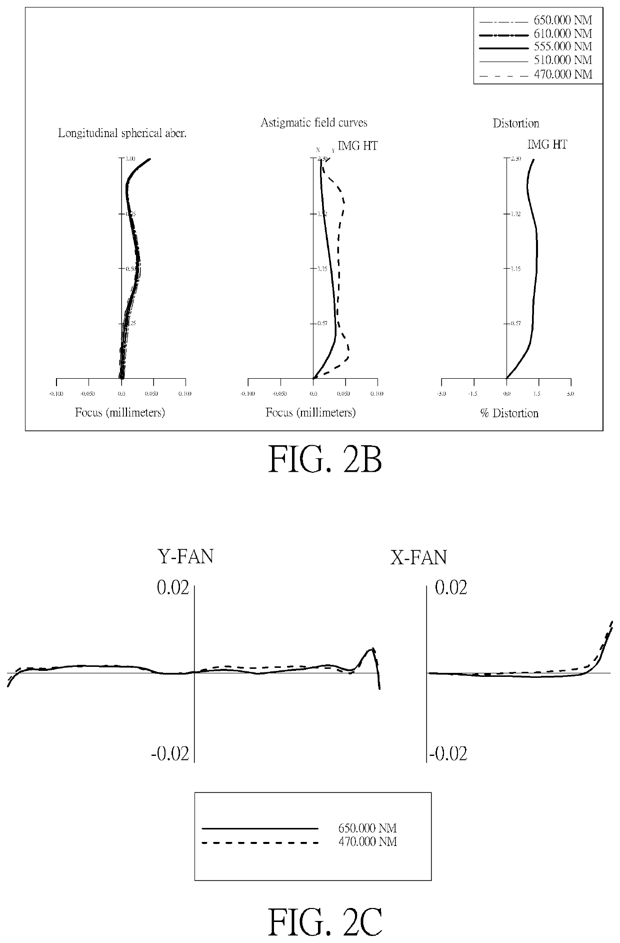
[0138]Please refer to FIGS. 2A and 2B, wherein FIG. 2A is a schematic view of the optical image capturing system according to the second embodiment of the present disclosure. FIG. 2B is a curve diagram illustrating the spherical aberration, astigmatism and optical distortion of the optical image capturing system in sequence from left to right according to the second embodiment of the present disclosure. FIG. 2C is a transverse aberration diagram of the longest operation wavelength and the shortest operation wavelength for tangential fan and sagittal fan, of which the longest operation wavelength and the shortest operation wavelength pass through an edge of aperture at the position of 0.7 field of view on the image plane according to the second embodiment of the present disclosure. As shown in FIG. 2A, in the order from an object side to an image side, the optical image capturing system includes a first lens 210, an aperture 200, a second lens 220, a third lens 230, a fourth lens 240, a fifth lens 250, an infrared filter 270, an image plane 280, and an image sensing device 290.
[0139]An electronic device configured with the present embodiment may be provided with a light admitting opening 201 on the object side, wherein the light admitting opening 201 is configured to limit an optical path from the object side. The light admitting opening 201 has a diameter denoted as DDH, wherein DDH=1.967 mm. The light admitting opening 201 is at a distance of 0.2 mm away from a center of the first lens 210 (where the optical axis passes) on the object side.
[0140]The first lens 210 has positive refractive power and is made of glass material. The first lens 210 has a flat object-side surface 212 and a flat image-side surface 214, wherein both of the surfaces are plate glass and have a focal length of infinity (INF).
[0141]The second lens 220 has positive refractive power and is made of plastic material. The second lens 220 has a convex object-side surface 222 and a convex image-side surface 224, wherein both of the surfaces are aspheric. The object-side surface 222 has two inflection points and the image-side surface 224 has one inflection points
[0142]The third lens 230 has negative refractive power and is made of plastic material. The third lens 230 has a concave object-side surface 232 and a concave image-side surface 234, wherein both of the surfaces are aspheric. The object-side surface 232 has three inflection points and the image-side surface 234 has one inflection point.
[0143]The fourth lens 240 has positive refractive power and is made of plastic material. The fourth lens 240 has a concave object-side surface 242 and a convex image-side surface 244, wherein both of the surfaces are aspheric. The object-side surface 242 has two inflection points and the image-side surface 244 has one inflection point.
[0144]The fifth lens 250 has negative refractive power and is made of plastic material. The fifth lens 250 has a convex object-side surface 252 and a concave image-side surface 254, wherein both of the surfaces are aspheric. The object-side surface 252 has two inflection points and the image-side surface 254 has one inflection point. Hence, the optical image capturing system is capable of effectively reducing an incident angle of the off-axis FOV rays, thereby further correcting an off-axis FOV aberration.
[0145]The infrared filter 270 is made of glass material and is configured between the fifth lens 250 and the image plane 290. The infrared filter 270 does not affect the focal length of the optical image capturing system.
[0146]Table 3 and Table 4 below should be incorporated into the reference of the present embodiment.
TABLE 3 Lens parameters of the second embodiment f(focal length) = 2.6276 mm; f/HEP = 2.42; HAF(half angle of view) = 40.5655 deg. Surface Thickness Refractive Abbe Focal No. Curvature Radius (mm) Material Index No. Length 0 Object 1E+18 1E+18 1 Lens 1 1E+18 0.900 Plate glass 2.001 25.44 INF 2 1E+18 0.079 3 Aperture 1E+18 −0.005 4 Lens 2 2.011534376 0.724 Plastic 1.5365 55.885 2.096 5 −2.245428184 0.052 6 Lens 3 −15.16428761 0.201 Plastic 1.661 20.390 −4.399 7 3.656060391 0.411 8 Lens 4 −1.808139481 0.715 Plastic 1.5365 55.885 1.820 9 −0.723417212 0.035 10 Lens 5 3.251740212 0.566 Plastic 1.5365 55.885 −1.781 11 0.695171313 0.385 12 Infrared 1E+18 0.210 NBK7 Filter 13 1E+18 0.468 14 Image 1E+18 0.000 Plane Reference wavelength = 555 nm; shield position: none
TABLE 4 aspheric coefficients of the second embodiment Table 4: aspheric coefficients Surface No. 1 2 4 5 6 7 8 k 0.000000E+00 0.000000E+00 −1.055302E+02 −3.320822E+01 6.823128E+01 −1.283688E+02 −6.261868E+00 A4 0.000000E+00 0.000000E+00 1.544889E+00 −3.488536E−01 1.360689E−01 4.729464E−01 −1.447585E−01 A6 0.000000E+00 0.000000E+00 −1.699897E+01 −7.916512E−01 −3.006572E+00 −3.038738E+00 1.974023E+00 A8 0.000000E+00 0.000000E+00 1.541496E+02 5.191618E+00 1.770200E+01 1.535044E+01 −1.902085E+01 A10 0.000000E+00 0.000000E+00 −1.007372E+03 −1.159425E+01 −6.806193E+01 −6.057158E+01 9.696502E+01 A12 0.000000E+00 0.000000E+00 4.418588E+03 1.622544E+01 1.960053E+02 1.714816E+02 −3.034269E+02 A14 0.000000E+00 0.000000E+00 −1.251639E+04 −2.196937E+01 −3.795478E+02 −3.175374E+02 5.921085E+02 A16 0.000000E+00 0.000000E+00 2.173795E+04 1.619696E+01 4.337228E+02 3.589806E+02 −7.040126E+02 A18 0.000000E+00 0.000000E+00 −2.095042E+04 0.000000E+00 −2.531546E+02 −2.230358E+02 4.694851E+02 A20 0.000000E+00 0.000000E+00 8.605635E+03 0.000000E+00 5.494106E+01 5.778849E+01 −1.350431E+02 Surface No. 9 10 11 k −1.026755E+00 −2.075678E+02 −4.716032E+00 A4 4.291564E−01 1.362519E−01 −1.427517E−01 A6 −5.381552E−01 −1.060854E+00 7.674481E−02 A8 −4.410170E−01 2.231366E+00 −1.617988E−02 A10 2.499179E+00 −2.724473E+00 −1.282651E−02 A12 −2.705181E+00 2.085101E+00 1.184540E−02 A14 −5.703397E−01 −1.000009E+00 −4.688743E−03 A16 3.188670E+00 2.898341E−01 1.071571E−03 A18 −2.135400E+00 −4.599700E−02 −1.390997E−04 A20 4.396995E−01 3.026761E−03 7.991373E−06
[0147]In the second embodiment, the form of the aspheric surface equation therein is presented as that in the first embodiment. In addition, the definition of parameters in the following tables is equivalent to that in the first embodiment, so that the repetitive details are not stated here.
[0148]The following conditional values may be obtained according to the data in Table 3 and Table 4.
Second embodiment (primary reference wavelength = 555 nm) |f/f1| |f/f2| |f/f3| |f/f4| |f/f5| |f1/f2| 0 1.25364 0.59730 1.44334 1.47550 INF ΣPPR ΣNPR ΣPPR/|ΣNPR| IN12/f IN45/f |f2/f3| 2.6970 0 0 0.0279 0.0133 0.4764 TP3/(IN23 + TP3 + IN34) (TP1 + IN12)/TP2 (TP5 + IN45)/TP4 0.30200 1.34473 0.84123 HOS InTL HOS/HOI InS/HOS ODT % TDT % 4.74000 3.67748 2.06356 0.79354 1.47256 0.419319 HVT11 HVT12 HVT21 HVT22 HVT31 HVT32 0 0 0 0 0 0 HVT41 HVT42 HVT51 HVT52 HVT52/HOI HVT52/HOS 0 1.07048 0.57381 1.33326 0.24981 0.12106 TP2/TP3 TP3/TP4 InRS51 InRS52 |InRS51|/TP5 |InRS52|/TP5 3.60956 0.28044 −0.150744 0.131004 0.26611 0.23126 PSTA PLTA NSTA NLTA SSTA SLTA −0.003 mm −0.004 mm −0.002 mm −0.003 mm 0.012 mm 0.010 mm
[0149]The values pertaining to the outline curve lengths may be obtained according to data in Table 3 and Table 4:
Second embodiment (primary reference wavelength = 555 nm) ARE ARE- 2(ARE/ ARE/ ARE 1/2(HEP) value 1/2(HEP) HEP) % TP TP (%) 11 0.546 0.545 −0.00070 99.87% 0.900 60.56% 12 0.546 0.545 −0.00070 99.87% 0.900 60.56% 21 0.546 0.550 0.00439 100.81% 0.724 76.00% 22 0.546 0.553 0.00747 101.37% 0.724 76.43% 31 0.546 0.545 −0.00025 99.95% 0.201 272.03% 32 0.546 0.547 0.00120 100.22% 0.201 272.75% 41 0.546 0.553 0.00739 101.35% 0.715 77.36% 42 0.546 0.581 0.03546 106.50% 0.715 81.28% 51 0.546 0.546 −0.00019 99.97% 0.566 96.30% 52 0.546 0.566 0.02027 103.71% 0.566 99.91% ARS ARS- (ARS/ ARS/ ARS EHD value EHD EHD)% TP TP (%) 11 0.931 0.931 −0.00019 99.98% 0.900 103.44% 12 0.615 0.615 −0.00039 99.94% 0.900 68.33% 21 0.608 0.614 0.00623 101.02% 0.724 84.87% 22 0.769 0.803 0.03448 104.48% 0.724 111.01% 31 0.818 0.819 0.00060 100.07% 0.201 408.49% 32 0.871 0.878 0.00718 100.83% 0.201 437.76% 41 0.891 0.933 0.04236 104.75% 0.715 130.54% 42 1.088 1.237 0.14952 113.75% 0.715 173.01% 51 1.486 1.508 0.02212 101.49% 0.566 266.25% 52 1.960 2.059 0.09852 105.03% 0.566 363.39%
[0150]The following values may be obtained according to the data in Table 3 and Table 4.
Values related to inflection point of second embodiment (primary reference wavelength = 555 nm) HIF211 0.5049 HIF211/HOI 0.2198 SGI211 0.0584 |SGI211|/(|SGI211| + TP2) 0.0747 HIF212 0.5833 HIF212/HOI 0.2539 SGI212 0.0737 |SGI212|/(|SGI212| + TP2) 0.0925 HIF221 0.7451 HIF221/HOI 0.3244 SGI221 −0.1761 |SGI221|/(|SGI221| + TP2) 0.1957 HIF311 0.5291 HIF311/HOI 0.2304 SGI311 −0.0160 |SGI311|/(|SGI311| + TP3) 0.0738 HIF312 0.6369 HIF312/HOI 0.2773 SGI312 −0.0237 |SGI312|/(|SGI312| + TP3) 0.1058 HIF313 0.7277 HIF313/HOI 0.3168 SGI313 −0.0303 |SGI313|/(|SGI313| + TP3) 0.1314 HIF321 0.7937 HIF321/HOI 0.3455 SGI321 0.0864 |SGI321|/(|SGI321| + TP3) 0.3012 HIF411 0.7630 HIF411/HOI 0.3322 SGI411 −0.1744 |SGI411|/(|SGI411| + TP4) 0.1961 HIF412 0.8420 HIF412/HOI 0.3666 SGI412 −0.2131 |SGI412|/(|SGI412| + TP4) 0.2296 HIF421 0.8508 HIF421/HOI 0.3704 SGI421 −0.4067 |SGI421|/(|SGI421| + TP4) 0.3626 HIF511 0.3219 HIF511/HOI 0.1402 SGI511 0.0121 |SGI511|/(|SGI511| + TP5) 0.0210 HIF512 1.1808 HIF512/HOI 0.5141 SGI512 −0.0830 |SGI512|/(|SGI512| + TP) 0.1278 HIF521 0.4930 HIF521/HOI 0.2146 SGI521 0.1224 |SGI521|/(|SGI521| + TP5) 0.1777

Example

Third Embodiment
[0151]Please refer to FIGS. 3A and 3B, wherein FIG. 3A is a schematic view of the optical image capturing system according to the third embodiment of the present disclosure. FIG. 3B is a curve diagram illustrating the spherical aberration, astigmatism and optical distortion of the optical image capturing system in sequence from left to right according to the third embodiment of the present disclosure. FIG. 3C is a transverse aberration diagram of the longest operation wavelength and the shortest operation wavelength for tangential fan and sagittal fan, of which the longest operation wavelength and the shortest operation wavelength pass through an edge of aperture at the position of 0.7 field of view on the image plane according to the third embodiment of the present disclosure. As shown in FIG. 3A, in the order from an object side to an image side, the optical image capturing system includes a first lens 310, an aperture 300, a second lens 320, a third lens 330, a fourth lens 340, a fifth lens 350, an infrared filter 370, an image plane 380 and an image sensing device 390.
[0152]An electronic device configured with the present embodiment may be provided with a light admitting opening 301 on the object side, wherein the light admitting opening 301 is configured to limit an optical path from the object side. The light admitting opening 301 has a diameter denoted as DDH, wherein DDH=1.962 mm. The light admitting opening 301 is at a distance of 0.2 mm away from a center of the first lens 310 (where the optical axis passes) on the object side.
[0153]The first lens 310 has positive refractive power and is made of glass material. The first lens 310 has a flat object-side surface 312 and a flat image-side surface 314, wherein both of the surfaces are plate glass and have a focal length of infinity (INF).
[0154]The second lens 320 has positive refractive power and is made of plastic material. The second lens 320 has a convex object-side surface 322 and a convex image-side surface 324, wherein both of the surfaces are aspheric. The object-side surface 322 has one inflection point.
[0155]The third lens 330 has negative refractive power and is made of plastic material. The third lens 330 has a convex object-side surface 332 and a concave image-side surface 334, wherein both of the surfaces are aspheric. The object-side surface 332 has two inflection points and the image-side surface 334 has three inflection points.
[0156]The fourth lens 340 has positive refractive power and is made of plastic material. The fourth lens 340 has a concave object-side surface 342 and a convex image-side surface 344, wherein both of the surfaces are aspheric. The object-side surface 342 has two inflection points and the image-side surface 344 has one inflection point.
[0157]The fifth lens 350 has negative refractive power and is made of plastic material. The fifth lens 350 has a convex object-side surface 352 and a concave image-side surface 354, wherein both of the surfaces are aspheric. The object-side surface 352 has two inflection points and the image-side surface 354 has one inflection point. In this manner, the back focal length may be reduced to maintain a miniaturized optical image capturing system.
[0158]The infrared filter 370 is made of glass material and is configured between the fifth lens 350 and the image plane 380. The infrared filter 370 does not affect the focal length of the optical image capturing system.
[0159]Table 5 and Table 6 below should be incorporated into the reference of the present embodiment.
TABLE 5 Lens parameters of the third embodiment f(focal length) = 1.6610 mm; f/HEP = 2.0; HAF(half angle of view) = 40.6930 deg Surface Thickness Refractive Abbe Focal No. Curvature Radius (mm) Material Index No. Length 0 Object 1E+18 1E+18 1 Lens 1 1E+18 0.900 Plate glass 2.998 90.36 INF 2 1E+18 0.074 3 Aperture 1E+18 0.016 4 Lens 2 1.937164325 0.551 Plastic 1.5365 55.885 3.242 5 −15.86643165 0.169 6 Lens 3 7.043863879 0.296 Plastic 1.661 20.390 −7.783 7 2.937983091 0.305 8 Lens 4 −4.653757573 0.760 Plastic 1.5365 55.885 2.128 9 −0.971581623 0.153 10 Lens 5 1.53438413 0.470 Plastic 1.5365 55.885 −2.427 11 0.629922364 0.366 12 Infrared 1E+18 0.210 BK_7 1.517 23.89 Filter 13 1E+18 0.480 14 Image 1E+18 0.000 Plane Reference wavelength = 555 nm; shield position: the 6th surface with clear aperture of 0.815 mm
TABLE 6 aspheric coefficients of the third embodiment Table 6: aspheric coefficients Surface No. 1 2 4 5 6 7 8 k 0.000000E+00 0.000000E+00 −4.004687E+00 3.608762E+02 −4.000000E+02 −6.334555E+01 −4.508144E+01 A4 0.000000E+00 0.000000E+00 9.129850E−02 −2.688215E−01 −1.988497E−01 2.890325E−01 1.560892E−01 A6 0.000000E+00 0.000000E+00 −1.820015E+00 −2.121676E−01 −1.931647E+00 −2.623986E+00 −1.201041E−01 A8 0.000000E+00 0.000000E+00 1.881727E+01 −1.992862E+00 1.222278E+01 1.250039E+01 −1.148695E+00 A10 0.000000E+00 0.000000E+00 −1.184064E+02 2.957956E+01 −5.702452E+01 −4.256193E+01 6.919439E+00 A12 0.000000E+00 0.000000E+00 4.221946E+02 −1.501775E+02 2.006252E+02 1.009215E+02 −1.966532E+01 A14 0.000000E+00 0.000000E+00 −7.390495E+02 4.195713E+02 −4.571782E+02 −1.565431E+02 3.244420E+01 A16 0.000000E+00 0.000000E+00 1.156617E+02 −6.931005E+02 6.222761E+02 1.494190E+02 −3.122865E+01 A18 0.000000E+00 0.000000E+00 1.492940E+03 6.340423E+02 −4.572885E+02 −7.915878E+01 1.623600E+01 A20 0.000000E+00 0.000000E+00 −1.521109E+03 −2.452217E+02 1.391861E+02 1.773861E+01 −3.533914E+00 Surface No. 9 10 11 k −2.073341E+00 −4.639375E+01 −4.452086E+00 A4 −4.079969E−01 −2.202709E−01 −1.585045E−01 A6 2.935648E+00 1.219414E−01 7.984346E−02 A8 −1.145722E+01 −3.318289E−01 4.333790E−05 A10 2.773957E+01 8.789094E−01 −3.976581E−02 A12 −4.238360E+01 −1.218423E+00 3.344777E−02 A14 4.089886E+01 9.475739E−01 −1.472892E−02 A16 −2.402211E+01 −4.176133E−01 3.799070E−03 A18 7.818257E+00 9.754443E−02 −5.402033E−04 A20 −1.081024E+00 −9.394648E−03 3.261679E−05
[0160]In the third embodiment, the form of the aspheric surface equation therein is presented as that in the first embodiment. In addition, the definition of parameters in the following tables is equivalent to that in the first embodiment, so that the repetitive details are not stated here.
[0161]The following values for the conditional expressions may be obtained from the data in Table 5 and Table 6.
Third embodiment (primary reference wavelength = 555 nm) |f/f1| |f/f2| |f/f3| |f/f4| |f/f5| |f1/f2| 0 0.81080 0.33778 1.23561 1.08333 INF ΣPPR ΣNPR ΣPPR/|ΣNPR| IN12/f IN45/f f2/f3 3.1297 0 0 0.0342 0.0583 0.4166 TP3/(IN23 + TP3 + IN34) (TP1 + IN12)/TP2 (TP5 + IN45)/TP4 0.38439 1.79775 0.82032 HOS InTL HOS/HOI InS/HOS ODT % TDT % 4.75000 3.69354 2.06791 0.79501 1.42365 0.625041 HVT11 HVT12 HVT21 HVT22 HVT31 HVT32 0 0 0 0 0.288619 0 HVT41 HVT42 HVT51 HVT52 HVT52/HOI HVT52/HOS 0.76304 1.07520 0.57003 1.30625 0.24816 0.12001 TP2/TP3 TP3/TP4 InRS51 InRS52 |InRS51|/TP5 |InRS52|/TP5 1.86077 0.38932 −0.198943 0.0933008 0.42316 0.19845 PSTA PLTA NSTA NLTA SSTA SLTA −0.007 mm 0.010 mm 0.001 mm −0.002 mm 0.005 mm 0.002 mm
[0162]The values pertaining to the outline curve lengths may be obtained from the data in Table 5 and Table 6:
Third embodiment (primary reference wavelength = 555 nm) ARE ARE- 2(ARE/ ARE/ ARE 1/2(HEP) value 1/2(HEP) HEP) % TP TP (%) 11 0.545 0.545 −0.00049 99.91% 0.900 60.56% 12 0.545 0.545 −0.00049 99.91% 0.900 60.56% 21 0.545 0.551 0.00531 100.97% 0.551 100.04% 22 0.545 0.547 0.00188 100.35% 0.551 99.42% 31 0.545 0.546 0.00051 100.09% 0.296 184.53% 32 0.545 0.547 0.00102 100.19% 0.296 184.70% 41 0.545 0.545 −0.00011 99.98% 0.760 71.76% 42 0.545 0.570 0.02464 104.52% 0.760 75.02% 51 0.545 0.546 0.00093 100.17% 0.470 116.22% 52 0.545 0.569 0.02327 104.27% 0.470 120.98% ARS ARS- (ARS/ ARS/ ARS EHD value EHD EHD)% TP TP (%) 11 0.816 0.815 −0.00083 99.90% 0.900 90.56% 12 0.611 0.611 −0.00015 99.97% 0.900 67.89% 21 0.637 0.644 0.00701 101.10% 0.551 116.95% 22 0.757 0.773 0.01654 102.19% 0.551 140.43% 31 0.815 0.821 0.00686 100.84% 0.296 277.62% 32 0.918 0.921 0.00241 100.26% 0.296 311.19% 41 1.024 1.025 0.00075 100.07% 0.760 134.84% 42 1.182 1.265 0.08277 107.00% 0.760 166.45% 51 1.509 1.547 0.03809 102.52% 0.470 328.98% 52 1.955 2.072 0.11743 106.01% 0.470 440.77%
[0163]The following values may be obtained according to the data in Table 5 and Table 6.
Values related to inflection point of third embodiment (primary reference wavelength = 555 nm) HIF211 0.5353 HIF211/HOI 0.2330 SGI211 0.0684 |SGI211|/(|SGI211| + TP2) 0.1106 HIF311 0.1699 HIF311/HOI 0.0740 SGI311 0.0017 |SGI311|/(|SGI311| + TP3) 0.0058 HIF312 0.7017 HIF312/HOI 0.3055 SGI312 −0.0494 |SGI312|/(|SGI312| + TP3) 0.1431 HIF321 0.4065 HIF321/HOI 0.1770 SGI321 0.0244 |SGI321|/(|SGI321| + TP3) 0.0762 HIF322 0.6883 HIF322/HOI 0.2997 SGI322 0.0484 |SGI322|/(|SGI322| + TP3) 0.1407 HIF323 0.8768 HIF323/HOI 0.3817 SGI323 0.0639 |SGI323|/(|SGI323| + TP3) 0.1776 HIF411 0.3671 HIF411/HOI 0.1598 SGI411 −0.0112 |SGI411|/(|SGI411| + TP4) 0.0146 HIF412 0.9063 HIF412/HOI 0.3946 SGI412 −0.0205 |SGI412|/(|SGI412| + TP4) 0.0263 HIF421 0.7422 HIF421/HOI 0.3231 SGI421 −0.2549 |SGI421|/(|SGI421| + TP4) 0.2512 HIF511 0.2684 HIF511/HOI 0.1168 SGI511 0.0173 |SGI511|/(|SGI511| + TP5) 0.0356 HIF512 1.1659 HIF512/HOI 0.5076 SGI512 −0.0976 |SGI512|/(|SGI512| + TP5) 0.1719 HIF521 0.4736 HIF521/HOI 0.2062 SGI521 0.1239 |SGI521|/(|SGI521| + TP5) 0.2086

PUM

no PUM

Description & Claims & Application Information

We can also present the details of the Description, Claims and Application information to help users get a comprehensive understanding of the technical details of the patent, such as background art, summary of invention, brief description of drawings, description of embodiments, and other original content. On the other hand, users can also determine the specific scope of protection of the technology through the list of claims; as well as understand the changes in the life cycle of the technology with the presentation of the patent timeline. Login to view more.

Similar technology patents

Catadioptric Objective for Scatterometry

ActiveUS20130170049A1aberration correction
Owner:ASML HLDG NV

Compensation Of Optical Aberrations Caused By Non-Planar Windows

ActiveUS20140293425A1aberration correction
Owner:NOKIA TECHNOLOGLES OY

Multi-mirror heliostat

InactiveUS20150185433A1prevents aberrationincrease in size
Owner:MITAKA KOHKI

Imaging lens

ActiveUS20120162769A1small poweraberration correction
Owner:TOKYO VISIONARY OPTICS CO LTD

Ocular optics system having at least four reflections occurring between curved surfaces

InactiveUSRE37169E1aberration correctionlight weight
Owner:OLYMPUS OPTICAL CO LTD

Classification and recommendation of technical efficacy words

  • prevents aberration

Multi-mirror heliostat

InactiveUS20150185433A1prevents aberrationincrease in size
Owner:MITAKA KOHKI
Why Eureka
Try Eureka