Mobile device and optical imaging lens thereof

Active Publication Date: 2014-03-13
GENIUS ELECTRONICS OPTICAL CO LTD
View PDF5 Cites 2 Cited by
  • Summary
  • Abstract
  • Description
  • Claims
  • Application Information

AI Technical Summary

Benefits of technology

[0015]Through a ratio control among at least one central thickness of lens element along the optical axis, an air gap between two adjacent lens elements along the optical axis, and the sum of all air gaps between the four lens elements along the optical axis in a predetermined range, and together

Problems solved by technology

When reducing the size of the optical imaging lens, however, achieving good optical characteristics becomes a challenging problem.
The excessive sum of all air gaps between the lens elements is unfavorable for endeavoring slimmer mobile dev

Method used


Image

  • Mobile device and optical imaging lens thereof
  • Mobile device and optical imaging lens thereof
  • Mobile device and optical imaging lens thereof

Examples


first embodiment

[0101]Reference is now made to FIG. 27, which illustrates an example structural view of mobile device 20 applying an aforesaid optical imaging lens. The mobile device 20 comprises a housing 2100 and an optical imaging lens assembly 2200 disposed in the housing 210. An example of the mobile device 20 may be, but is not limited to, a mobile phone.

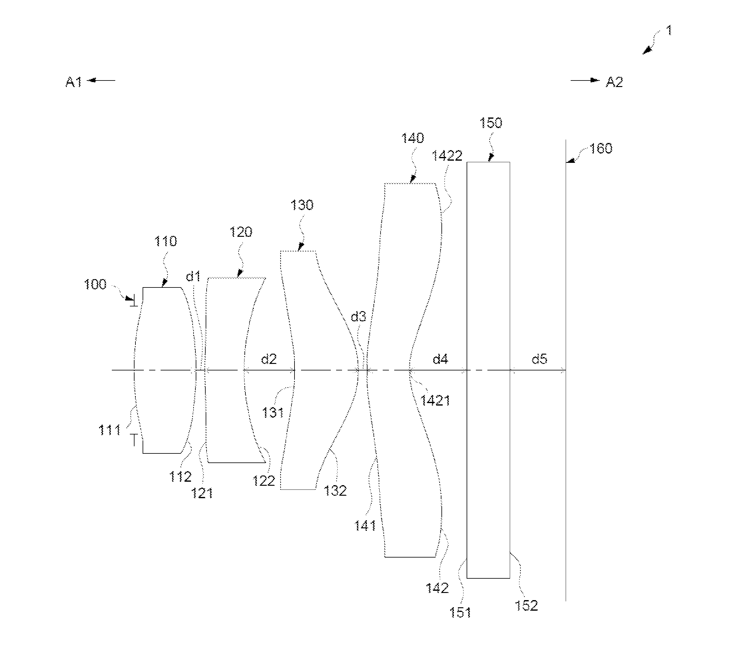
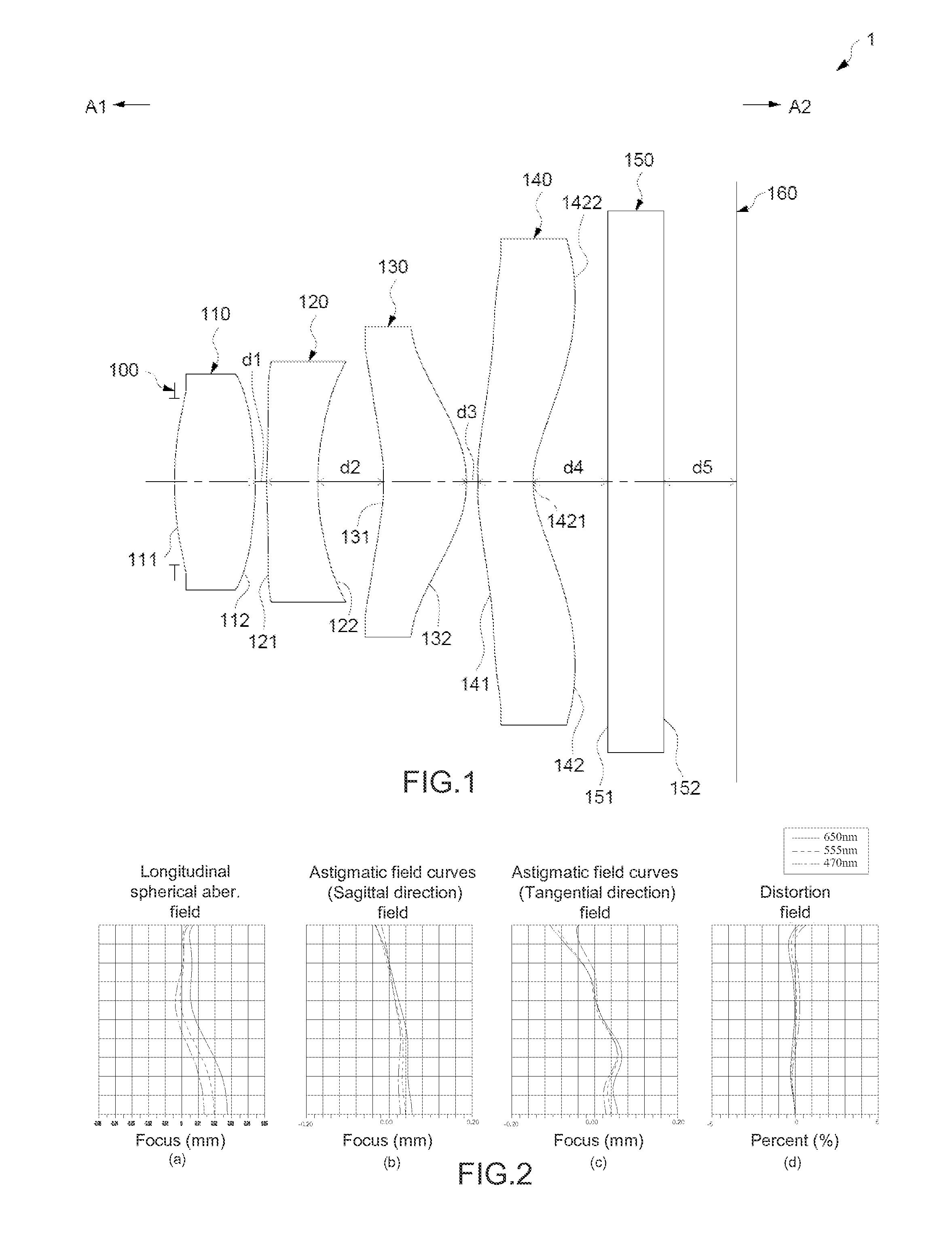
[0102]As shown in FIG. 27, the optical imaging lens assembly 2200 may comprise an aforesaid optical imaging lens, for example the optical imaging lens 1 of the first embodiment, a lens barrel 2300 for positioning the optical imaging lens 1, a module housing unit 2400 for positioning the lens barrel 230, and an image sensor 161 which is positioned at an image side of the optical imaging lens 1. The image plane 160 is formed on the image sensor 161.

[0103]In some example embodiments, the structure of the filtering unit 150 may be omitted. In some example embodiments, the housing 210, the lens barrel 2300, and / or the module housing unit 2400 may ...

second embodiment

[0107]Reference is now made to FIG. 28, which shows another structural view of mobile device 22 applying the aforesaid optical imaging lens 1. One difference between the mobile device 22 and the mobile device 20 may be the module housing unit 2400 further comprising an autofocus module 2403. The autofocus module 2403 may comprise a lens seat 2404, a lens backseat 2401, a coil 2405, and a magnetic unit 2406. The lens seat 2404, which is close to the outside of the lens barrel 230, and the lens barrel 2300 are positioned along an axis II′, and the lens backseat 2401 is positioned along with the axis II′ and around the outside of the lens seat 2404. The coil 2405 is positioned between the lens seat 2404 and the inside of the lens backseat 2401. The magnetic unit 2406 is positioned between the outside of the coil 2405 and the inside of the lens backseat 2401.

[0108]The lens barrel 2300 and the optical imaging lens 1 disposed therein are driven by the lens seat 2404 for moving along the a...


PUM


Abstract

The present invention provides a mobile device and an optical imaging lens thereof. The optical imaging lens comprises an aperture stop, first, second, third and fourth lens elements positioned sequentially from an object side to an image side. The first lens element with positive refracting power has a surface facing toward the object side. The second lens element with negative refracting power has a convex surface facing toward the object. The third lens element has a positive refracting power. The fourth lens element has a surface facing toward the object side with a concave portion in the vicinity of the optical axis and a surface facing toward the image side with a convex portion in the peripheral vicinity. The optical imaging lens of the present invention is capable of shortening the total length of the optical imaging lens efficiently and has good optical characteristics.

Description

CROSS-REFERENCES TO RELATED APPLICATIONS[0001]This application claims priority to Chinese Patent Application No. 201210328571.9, filed on Sep. 9, 2012 and Chinese Patent Application No. 201210437198.0, filed on Nov. 6, 2012, the contents of which are hereby incorporated by reference in their entirety for all purposes.BACKGROUND OF THE INVENTION[0002]The present invention relates to a mobile device and an optical imaging lens thereof, and particularly, relates to a mobile device applying an optical imaging lens having four lens elements and an optical imaging lens thereof.[0003]The ever-increasing demand for smaller sized mobile devices, such as cell phones, digital cameras, etc. has correspondingly triggered a growing need for smaller sized photography modules contained therein. Size reductions may be contributed from various aspects of the mobile devices, which includes not only the charge coupled device (CCD) and the complementary metal-oxide semiconductor (CMOS), but also the opt...

Claims


Application Information

Patent Timeline
IPC IPC(8): G02B9/34H04N5/225
CPCH04N5/2254G02B9/34G02B13/18G02B3/00G02B13/004H04N23/55
Inventor CHEN, SHIHHANCHEN, YANBINYE, LONG
Owner GENIUS ELECTRONICS OPTICAL CO LTD
Why Eureka
Try Eureka