Wide viewing angle optical lens assembly

Active Publication Date: 2012-08-23
LARGAN PRECISION
4 Cites 31 Cited by

AI-Extracted Technical Summary

Problems solved by technology

U.S. Pat. No. 6,490,102 provides a topical lens configuration with a three-element lens assembly comprising a glass lens and a plastic lens, where a third lens element is glass, such that the freedom of correcting the aberration of the topical lens assembly is reduced, thereby the image quality becomes difficult to control.
Furthermore...

Method used

[0067]When the wide viewing angle optical lens assembly 10 satisfies (Condition 1), the allocation of the refractive power between the second lens element 120 and the third lens element 130 is proper. The appropriate range satisfying (Condition 1) may be 0.82/f3<1.2. When the wide viewing angle optical lens assembly 10 satisfies (Condition 2), the curvature radius of the object-side surface 131 of the third lens element 130 is proper for correcting the aberration. When the wide viewing angle optical lens assembly 10 satisfies (Condition 3), the curvature radii of the third lens element 130 are proper, thereby enhancing the positive refractive power and reducing the aberration. The appropriate range satisfying (Condition 3) may be 0.4<(R5+R6)/(R5−R6)<2.0. When the wide viewing angle optical lens assembly 10 satisfies (Condition 4), the curvature radius of the object-side surface 112 of the first lens element 110 is proper for correcting the aberration. When the wide viewing angle optical lens assembly 10 satisfies (Condition 5), an improved wide field angle of the wide viewing angle optical lens assembly 10 can favorably be achieved. When the wide viewing angle optical lens assembly 10 satisfies (Condition 6), the ratio of the curvature radii between the second lens element 120 and the third lens elem...

Benefits of technology

[0014]In the above-mentioned wide viewing angle optical lens assembly, the first lens element with negative refractive power provides a greater angle of view. The second lens element with positive refractive power provides partial refractive power needed by the wide viewing angle optical lens assembly and shortens the total optical length of the same. The third lens element with positive refractive power works with the second lens element with the positive refractive power for effectively reducing the sensitivity of the wide viewing angle optical lens assembly.
[0015]Furthermore, since the second lens element has the convex object-side surface, the positive refractive power of the second lens element is enhanced, thereby reducing the total optical length of the wide viewing angle optical lens assembly. In addition, when the third lens element has the convex image-side surface, the total optical length of the wide viewing angle optical lens assembly may also be shortened.
[0016]When the wide viewing angle optical lens assembly satisfies (Condition 1), the allocation of the refractive power between the second lens element and th...

Abstract

A wide viewing angle optical lens assembly comprises, in order from an object side to an image side, a first lens element with negative refractive power having a convex object-side surface and a concave image-side surface, a second lens element with positive refractive power having a convex object-side surface, a third lens element with positive refractive power having a convex image-side surface. By adjusting the relationship among the above-mentioned lens elements, the wide viewing angle optical lens assembly can effectively reduce its size, obtain greater angle of view as well as superior imaging quality.

Application Domain

Technology Topic

Image

  • Wide viewing angle optical lens assembly
  • Wide viewing angle optical lens assembly
  • Wide viewing angle optical lens assembly

Examples

  • Experimental program(10)

Example

Embodiment 1
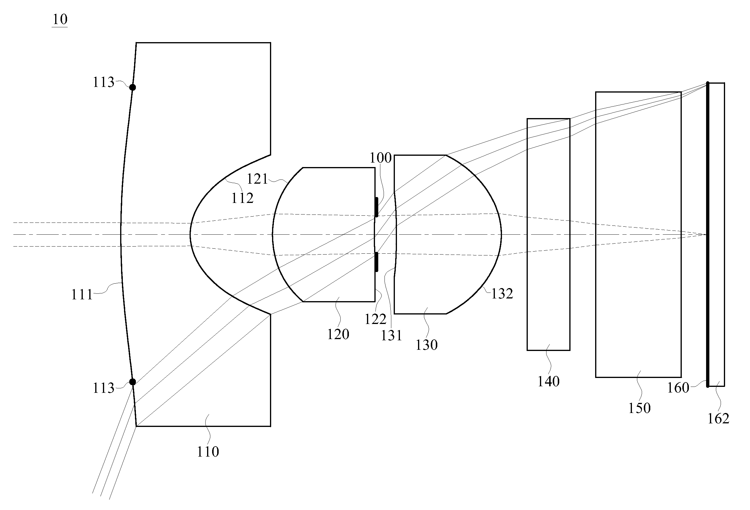
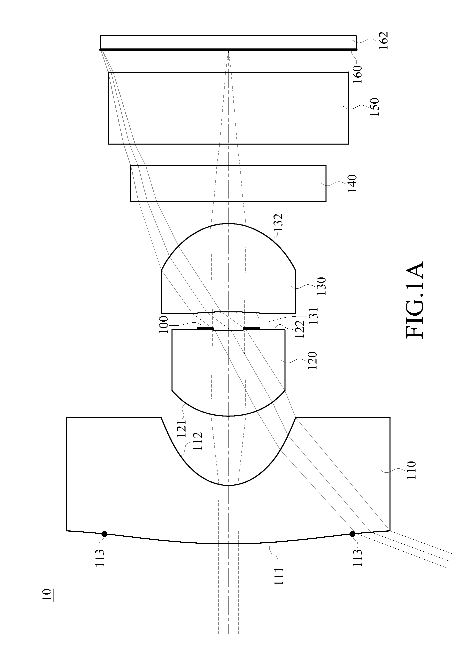
[0076]FIG. 1A is a schematic structural view of a first embodiment of a wide viewing angle optical lens assembly according to the present invention. In this embodiment, for example, the wavelength of the light received by the wide viewing angle optical lens assembly 10 is 587.6 nm, but the wavelength of the light received by the wide viewing angle optical lens assembly 10 may be adjusted according to actual requirements, and is not limited to the wavelength value mentioned above.
[0077]According to this embodiment of the present invention, the first lens element 110 has the negative refractive power, the second lens element 120 has the positive refractive power, and the third lens element 130 has the positive refractive power. Wherein, the object-side surface 111 of the first lens element 110 is convex and there are two inflection points 113 on the object-side surface 111 of the first lens element 110. The image-side surface 112 of the first lens element 110 is concave. The object-side surface 121 of the second lens element 120 is convex. The image-side surface 132 of the third lens element 130 is convex.
[0078]The detailed data of the wide viewing angle optical lens assembly 10 is as shown in Table 1-1 below.
TABLE 1-1 (Embodiment 1) f = 0.44 mm, Fno = 4.00, HFOV = 69.8 deg. Surface # Curvature Radius Thickness Material Index Abbe # Focal length 0 Object Plano Infinity 1 Lens 1 3.430300 (ASP) 0.324 Plastic 1.544 55.9 −0.50 2 0.244580 (ASP) 0.384 3 Lens 2 0.447710 (ASP) 0.475 Plastic 1.634 23.8 0.87 4 1.421600 (ASP) 0.011 5 Ape. Stop Plano 0.092 6 Lens 3 −4.171000 (ASP) 0.490 Plastic 1.514 56.8 0.68 7 −0.333250 (ASP) 0.120 8 IR-filter Plano 0.200 Glass 1.517 64.2 — 9 Plano 0.120 10 Cover Plano 0.400 Glass 1.517 64.2 — 11 Plano 0.124 12 Image Plano — Note: Reference wavelength is d-line 587.6 nm
[0079]Furthermore, the first lens element 110, the second lens element 120, and the third lens element 130 are aspheric, and the aspheric surfaces may satisfy Formula ASP, but are not limited thereto. As for the parameters of the aspheric surfaces, reference is made to Table 1-2 below.
TABLE 1-2 Aspheric Coefficients Surface# 1 2 3 4 6 7 k 1.88843E+00 −9.57219E−01 −1.55089E+00 −1.00000E+00 5.79795E+01 −7.78663E−01 A4 −6.25084E−03 3.27896E+00 2.97762E+00 7.14909E+00 −3.55947E+00 −6.49789E−01 A6 −2.29665E−01 −3.37180E+01 1.10426E+01 −1.35237E+03 −1.02957E+01 1.61031E+00 A8 2.29131E−01 7.07540E+02 1.21348E+02 1.69735E+05 8.47371E+02 −6.28308E+01 A10 −7.18359E−02 −2.93064E+03 −1.15225E+03 −7.04211E+06 −5.50679E+03 −1.04925E+02
[0080]The content of Table 1-3 may be deduced from Table 1-1.
TABLE 1-3 (Embodiment 1) f (mm) 0.44 R3/R6 −1.34 Fno 4.00 (R5 + R6)/(R5 − R6) 1.17 HFOV(deg.) 69.8 R2/f 0.56 R1/|R5| 0.82 f2/f3 1.28 R3/R4 0.31 SL/TTL 0.53
[0081]In this embodiment, the f2/f3 is 1.28, which satisfies the range of (Condition 1). The R1/|R5| is 0.82, which satisfies the range of (Condition 2). The (R5+R6)/(R5−R6) is 1.17, which satisfies the range of (Condition 3). The R2/f is 0.56, which satisfies the range of (Condition 4). The SL/TTL is 0.53, which satisfies the range of (Condition 5). The R3/R6 is −1.34, which satisfies the range of (Condition 6). The R3/R4 is 0.31, which satisfies the range of (Condition 7). The HFOV is 69.8, which satisfies the range of (Condition 8).
[0082]FIG. 1B is a schematic view of longitudinal spherical aberration curves when the lights having wavelengths of 486.1 nm, 587.6 nm, and 656.3 nm are respectively projected in the wide viewing angle optical lens assembly 10 in FIG. 1A. The longitudinal spherical aberration curve of the light having the wavelength of 486.1 nm in the wide viewing angle optical lens assembly 10 is indicated by a solid line L in FIG. 1B. The longitudinal spherical aberration curve of the light having the wavelength of 587.6 nm in the wide viewing angle optical lens assembly 10 is indicated by a dashed line M in FIG. 1B. The longitudinal spherical aberration curve of the light having the wavelength of 656.3 nm in the wide viewing angle optical lens assembly 10 is indicated by a dotted line N in FIG. 1B. Horizontal axis is the focus position (millimeter, mm), and longitudinal axis is the normalized entrance pupil or aperture value. In other words, the differences of the focus positions of the paraxial light (the longitudinal coordinate is close to 0) and the fringe light (the longitudinal coordinate is close to 1) after entering the wide viewing angle optical lens assembly 10 can be seen from the longitudinal spherical aberration curves. It can be known from FIG. 1B that, no matter the wavelength of the light received by the wide viewing angle optical lens assembly 10 of this embodiment is 486.1 nm, 587.6 nm, or 656.3 nm, the longitudinal spherical aberration generated by the wide viewing angle optical lens assembly 10 is within the range of −0.05 mm to 0.02 mm.
[0083]In the second embodiment to the tenth embodiment and the schematic views of the longitudinal spherical aberration curves in FIGS. 2B, 3B, 4B, 5B, 6B, 7B, 8B, 9B, and 10B, the solid line L indicates the longitudinal spherical aberration curve of the light having the wavelength of 486.1 nm, the dashed line M indicates the longitudinal spherical aberration curve of the light having the wavelength of 587.6 nm, and the dotted line N indicates the longitudinal spherical aberration curve of the light having the wavelength of 656.3 nm, which will not be repeated herein for sake of conciseness.
[0084]FIG. 1C is a schematic view of astigmatic field curves when the light having the wavelength of 587.6 nm is projected in the wide viewing angle optical lens assembly 10 in FIG. 1A. An astigmatic field curve of a tangential plane is a dashed line T in FIG. 1C. An astigmatic field curve of a sagittal plane is a solid line S in FIG. 1C. Horizontal axis is the focus position (mm), and longitudinal axis is the image height (mm). In other words, the differences of the focus positions due to different curvatures of the tangential plane and the sagittal plane can be seen from the astigmatic field curves. It can be known from FIG. 1C that, the astigmatic field curvature of the tangential plane generated when the light having the wavelength of 587.6 nm is projected in the wide viewing angle optical lens assembly 10 is within the range of −0.07 mm to 0.0 mm, and the astigmatic field curvature of the sagittal plane is within the range of −0.015 mm to 0.005 mm.
[0085]In the second embodiment to the tenth embodiment and the schematic views of the astigmatic field curves in FIGS. 2C, 3C, 4C, 5C, 6C, 7C, 8C, 9C, and 10C, the solid line S indicates the astigmatic field curve of the sagittal plane, and the dashed line T indicates the astigmatic field curve of the tangential plane, which will not be repeated herein for sake of conciseness.
[0086]FIG. 1D is a schematic view of a distortion curve when the light having the wavelength of 587.6 nm is projected in the wide viewing angle optical lens assembly in FIG. 1A. Horizontal axis is the distortion ratio (%), and longitudinal axis is the image height (mm). In other words, the differences of the distortion ratios caused by different image heights can be seen from the distortion curve G. It can be known from FIG. 1D that, the distortion ratio generated when the light having the wavelength of 587.6 nm is projected in the wide viewing angle optical lens assembly 10 is within the range of −40% to 0%. As shown in FIGS. 1B to 1D, the wide viewing angle optical lens assembly 10, designed according to the first embodiment, is capable of greater angle of view.
[0087]In the second embodiment to the tenth embodiment and the schematic views of the distortion curves in FIGS. 2D, 3D, 4D, 5D, 6D, 7D, 8D, 9D, and 10D, the solid line G indicates the distortion curve of the light having the wavelength of 587.6 nm, which will not be repeated herein for sake of conciseness.
[0088]It should be noted that, the distortion curves and the astigmatic field curves generated when the lights having the wavelength of 486.1 nm and 656.3 nm are projected in the wide viewing angle optical lens assembly 10 are close to the distortion curve and the astigmatic field curves generated when the light having the wavelength of 587.6 nm is projected in the wide viewing angle optical lens assembly 10. In order to prevent the confusion in FIGS. 1C and 1D, the distortion curve and the astigmatic field curves generated when the lights having the wavelength of 486.1 nm and 656.3 nm are projected in the wide viewing angle optical lens assembly 10 are not shown in FIGS. 1C and 1D, and the same is in the second embodiment to the tenth embodiment.

Example

Embodiment 2
[0089]FIG. 2A is a schematic structural view of a second embodiment of the wide viewing angle optical lens assembly according to the present invention. The specific implementation is substantially the same as that in the first embodiment, and the elements in the second embodiment are the same as those in the first embodiment, so that the element symbols all begin with “2” as the hundredth digit, which represents that the elements have the same function or structure. For sake of conciseness, only the differences are illustrated below, and the similar parts will not be repeated herein.
[0090]In this embodiment, for example, the wavelength of the light received by a wide viewing angle optical lens assembly 20 is 587.6 nm, but the wavelength of the light received by the wide viewing angle optical lens assembly 20 may be adjusted according to actual requirements, and is not limited to the wavelength value mentioned above.
[0091]According to this embodiment of the present invention, a first lens element 210 has negative refractive power, a second lens element 220 has positive refractive power, and a third lens element 230 has positive refractive power. Wherein, an object-side surface 211 of the first lens element 210 is convex and there are two inflection points 213 on the object-side surface 211 of the first lens element 210. An image-side surface 212 of the first lens element 210 is concave. An object-side surface 221 of the second lens element 220 is convex. An image-side surface 232 of the third lens element 230 is convex.
[0092]The detailed data of the wide viewing angle optical lens assembly 20 is as shown in Table 2-1 below.
TABLE 2-1 (Embodiment 2) f = 0.50 mm, Fno = 5.00, HFOV = 69.6 deg. Surface # Curvature Radius Thickness Material Index Abbe # Focal length 0 Object Plano Infinity 1 Lens 1 0.823420 (ASP) 0.300 Plastic 1.544 55.9 −0.45 2 0.164750 (ASP) 0.276 3 Lens 2 0.363560 (ASP) 0.344 Plastic 1.634 23.8 0.64 4 2.159110 (ASP) 0.026 5 Ape. Stop Plano 0.151 6 Lens 3 1.489520 (ASP) 0.491 Plastic 1.514 56.8 0.70 7 −0.422660 (ASP) 0.200 8 IR-filter Plano 0.300 Glass 1.517 64.2 — 9 Plano 0.221 10 Image Plano — Note: Reference wavelength is d-line 587.6 nm
[0093]Furthermore, the first lens element 210, the second lens element 220, and the third lens element 230 are aspheric, and the aspheric surfaces may satisfy Formula ASP, but are not limited thereto. As for the parameters of the aspheric surfaces, reference is made to Table 2-2 below.
TABLE 2-2 Aspheric Coefficients Surface# 1 2 3 4 6 7 k −8.15433E+00 −1.36827E+00 −5.49190E−01 −1.00000E+00 −1.18851E−03 −5.49285E+00 A4 −7.33094E−01 1.01951E+01 3.76590E+00 1.91646E+00 −6.72180E−01 −5.61596E+00 A6 7.83379E−01 1.36366E+01 −3.09376E+01 4.87924E+02 −1.72455E+01 4.47699E+01 A8 4.94383E−02 −6.66103E+02 7.82579E+02 −6.05374E+04 2.14620E+02 −2.20980E+02 A10 −3.14264E−01 3.06923E+03 −7.11208E+03 1.93394E+06 −7.30630E+02 4.20899E+02
[0094]The content of Table 2-3 may be deduced from Table 2-1.
TABLE 2-3 (Embodiment 2) f (mm) 0.50 R3/R6 −0.86 Fno 5.00 (R5 + R6)/(R5 − R6) 0.56 HFOV(deg.) 69.6 R2/f 0.33 R1/|R5| 0.55 f2/f3 0.91 R3/R4 0.17 SL/TTL 0.57
[0095]FIG. 2B is a schematic view of longitudinal spherical aberration curves when the lights having wavelengths of 486.1 nm, 587.6 nm, and 656.3 nm are respectively projected in the wide viewing angle optical lens assembly 20 in FIG. 2A. It can be known from FIG. 2B that, no matter the wavelength of the light received by the wide viewing angle optical lens assembly 20 of this embodiment is 486.1 nm, 587.6 nm, or 656.3 nm, the longitudinal spherical aberration generated by the wide viewing angle optical lens assembly 20 is within the range of −0.06 mm to 0.02 mm.
[0096]FIG. 2C is a schematic view of astigmatic field curves when the light having the wavelength of 587.6 nm is projected in the wide viewing angle optical lens assembly 20 in FIG. 2A. It can be known from FIG. 2C that, the astigmatic field curvature of the tangential plane generated when the light having the wavelength of 587.6 nm is projected in the wide viewing angle optical lens assembly 20 is within the range of −0.05 mm to 0.005 mm, and the astigmatic field curvature of the sagittal plane is within the range of −0.02 mm to 0.005 mm.
[0097]FIG. 2D is a schematic view of a distortion curve when the light having the wavelength of 587.6 nm is projected in the wide viewing angle optical lens assembly in FIG. 2A. It can be known from FIG. 2D that, the distortion ratio generated when the light having the wavelength of 587.6 nm is projected in the wide viewing angle optical lens assembly 20 is within the range of −50% to 0%. As shown in FIGS. 2B to 2D, the wide viewing angle optical lens assembly 20, designed according to the second embodiment, is capable of greater angle of view.

Example

Embodiment 3
[0098]FIG. 3A is a schematic structural view of a third embodiment of the wide viewing angle optical lens assembly according to the present invention. The specific implementation is substantially the same as that in the first embodiment, and the elements in the third embodiment are the same as those in the first embodiment, so that the element symbols all begin with “3” as the hundredth digit, which represents that the elements have the same function or structure. For sake of conciseness, only the differences are illustrated below, and the similar parts will not be repeated herein.
[0099]In this embodiment, for example, the wavelength of the light received by the wide viewing angle optical lens assembly 30 is 587.6 nm, but the wavelength of the light received by the wide viewing angle optical lens assembly 30 may be adjusted according to actual requirements, and is not limited to the wavelength value mentioned above.
[0100]According to this embodiment of the present invention, a first lens element 310 has negative refractive power, a second lens element 320 has positive refractive power, and a third lens element 330 has positive refractive power. Wherein, an object-side surface 311 of the first lens element 310 is convex and there are two inflection points 313 on the object-side surface 311 of the first lens element 310. An image-side surface 312 of the first lens element 310 is concave. An object-side surface 321 of the second lens element 320 is convex. An image-side surface 332 of the third lens element 330 is concave.
[0101]The detailed data of the wide viewing angle optical lens assembly 30 is as shown in Table 3-1 below.
TABLE 3-1 (Embodiment 3) f = 0.48 mm, Fno = 3.30, HFOV = 70.2 deg. Surface # Curvature Radius Thickness Material Index Abbe # Focal length 0 Object Plano Infinity 1 Lens 1 0.497380 (ASP) 0.280 Plastic 1.544 55.9 −0.59 2 0.156730 (ASP) 0.457 3 Lens 2 0.622090 (ASP) 0.368 Plastic 1.634 23.8 0.85 4 −3.225100 (ASP) 0.088 5 Ape. Stop Plano 0.143 6 Lens 3 2.347140 (ASP) 0.600 Plastic 1.514 55.9 0.79 7 −0.475800 (ASP) 0.200 8 IR-filter Plano 0.300 Glass 1.517 64.2 — 9 Plano 0.223 10 Image Plano — Note: Reference wavelength is d-line 587.6 nm
[0102]Furthermore, the first lens element 310, the second lens element 320, and the third lens element 330 are aspheric, and the aspheric surfaces may satisfy Formula ASP, but are not limited thereto. As for the parameters of the aspheric surfaces, reference is made to Table 3-2 below.
TABLE 3-2 Aspheric Coefficients Surface# 1 2 3 4 6 7 k −2.29634E+00 −1.54438E+00 −1.19739E+01 −1.00000E+00 −2.19352E+01 −8.19100E−01 A4 −9.79760E−01 1.41961E+01 6.38249E+00 1.43284E+00 −1.82759E−01 9.48496E−01 A6 3.73232E−01 −9.07072E+01 −3.65494E+01 −1.24097E+01 −4.77100E+01 7.54056E−01 A8 8.69685E−01 4.63226E+02 2.88566E+02 −6.97980E+02 8.57936E+02 −3.52508E+01 A10 −6.92527E−01 −1.30371E+03 −1.58650E+03 7.68277E+03 −4.43421E+03 1.19886E+02
[0103]The content of Table 3-3 may be deduced from Table 3-1.
TABLE 3-3 (Embodiment 3) f (mm) 0.48 R3/R6 −1.31 Fno 3.30 (R5 + R6)/(R5 − R6) 0.66 HFOV(deg.) 70.2 R2/f 0.33 R1/|R5| 0.21 f2/f3 1.08 R3/R4 −0.19 SL/TTL 0.53
[0104]FIG. 3B is a schematic view of longitudinal spherical aberration curves when the lights having a wavelength of 486.1 nm, 587.6 nm, and 656.3 nm are respectively projected in the wide viewing angle optical lens assembly 30 in FIG. 3A. It can be known from FIG. 3B that, no matter the wavelength of the light received by the wide viewing angle optical lens assembly 30 of this embodiment is 486.1 nm, 587.6 nm, or 656.3 nm, the longitudinal spherical aberration generated by the wide viewing angle optical lens assembly 30 is within the range of −0.05 mm to 0.02 mm.
[0105]FIG. 3C is a schematic view of astigmatic field curves when the light having the wavelength of 587.6 nm is projected in the wide viewing angle optical lens assembly 30 in FIG. 3A. It can be known from FIG. 3C that, the astigmatic field curvature of the tangential plane generated when the light having the wavelength of 587.6 nm is projected in the wide viewing angle optical lens assembly 30 is within the range of −0.02 mm to 0.02 mm, and the astigmatic field curvature of the sagittal plane is within the range of −0.025 mm to 0.005 mm.
[0106]FIG. 3D is a schematic view of a distortion curve when the light having the wavelength of 587.6 nm is projected in the wide viewing angle optical lens assembly in FIG. 3A. It can be known from FIG. 3D that, the distortion ratio generated when the light having the wavelength of 587.6 nm is projected in the wide viewing angle optical lens assembly 30 is within the range of −50% to 0%. As shown in FIGS. 3B to 3D, the wide viewing angle optical lens assembly 30, designed according to the third embodiment, is capable of greater angle of view.

PUM

no PUM

Description & Claims & Application Information

We can also present the details of the Description, Claims and Application information to help users get a comprehensive understanding of the technical details of the patent, such as background art, summary of invention, brief description of drawings, description of embodiments, and other original content. On the other hand, users can also determine the specific scope of protection of the technology through the list of claims; as well as understand the changes in the life cycle of the technology with the presentation of the patent timeline. Login to view more.

Similar technology patents

Tuning fork gyroscope

InactiveUS6862934B2Reduce sensitivityIncreased scale factorAcceleration measurement using interia forcesDecorative surface effectsTuning forkProof mass
Owner:CHARLES STARK DRAPER LABORATORY

Classification and recommendation of technical efficacy words

Why Eureka
Try Eureka