Terminal fitting

a technology of fittings and slits, applied in the direction of coupling contact members, coupling device connections, securing/insulating coupling contact members, etc., can solve the problems of easy stress concentration on the slit, easy crack formation with the slit as a base, and no slit needed to be provided, etc., to achieve the effect of easy formation

Active Publication Date: 2019-01-31
SUMITOMO WIRING SYST LTD
View PDF1 Cites 1 Cited by
  • Summary
  • Abstract
  • Description
  • Claims
  • Application Information

AI Technical Summary

Benefits of technology

[0008]The bending edge may extend straight from the front end of the bottom wall to the front end edge of the side wall. According to this configuration, the protection wall can be formed easily since the protection

Problems solved by technology

Further, stress easily concentrates on the slit, and a crack easily is formed with the slit as a base.
However, stress concentrates on the slit and easily can c

Method used


Image

  • Terminal fitting
  • Terminal fitting
  • Terminal fitting

Examples


Embodiment Construction

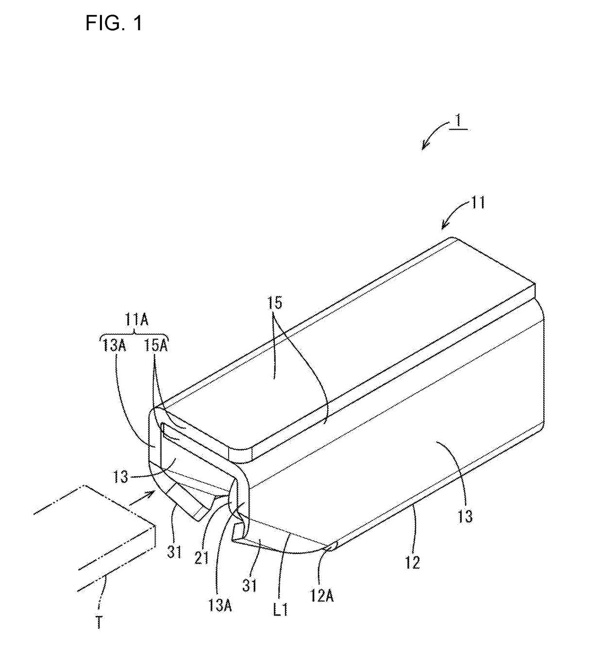
[0020]A first embodiment is described with reference to FIGS. 1 to 7. Note that only either one is described for bilaterally symmetrical structures and corresponding structures are denoted by the same reference signs.

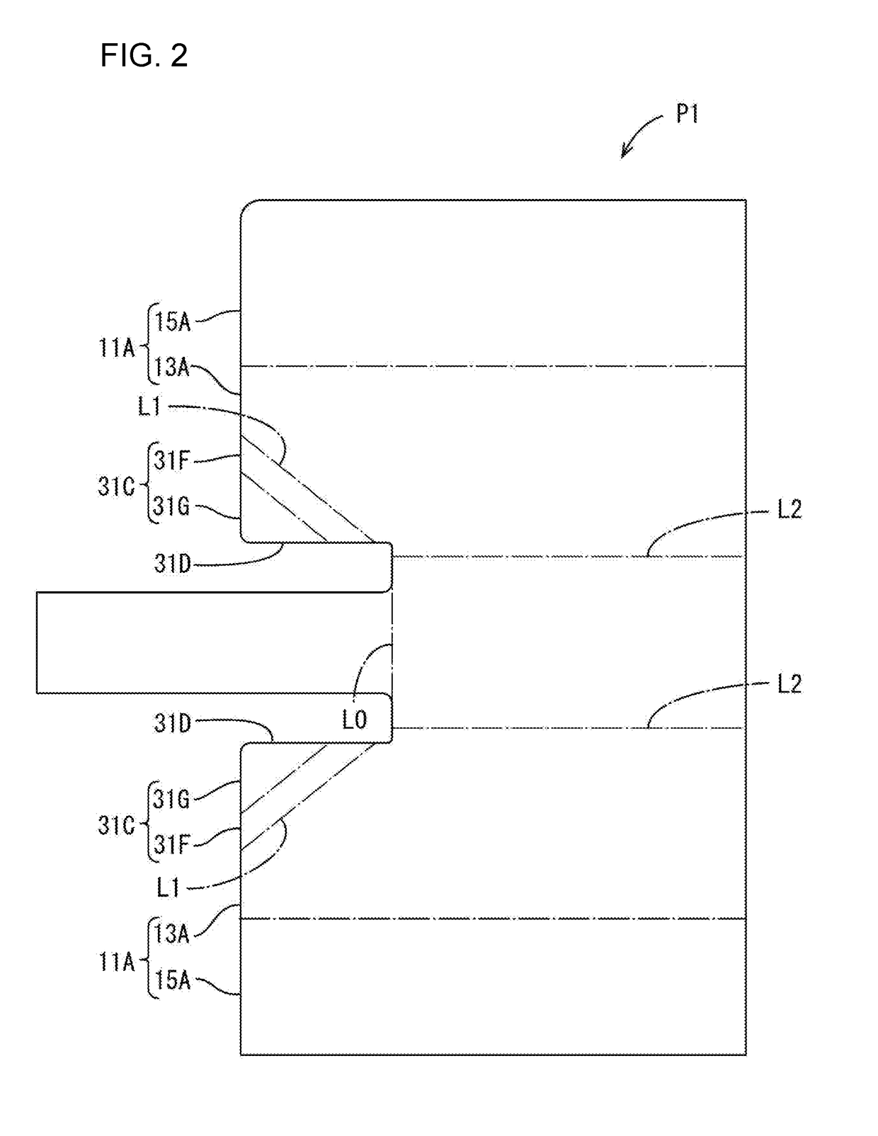
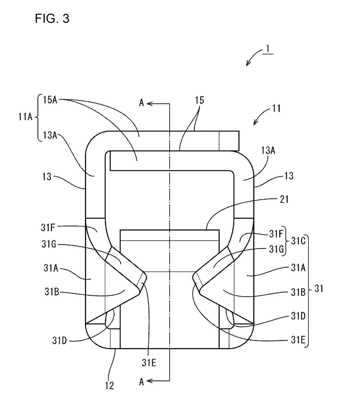
[0021]A terminal fitting 1 of this embodiment is a female terminal fitting to be connected to a mating male terminal fitting and is formed by stamping and bending a single metal plate material P1 shown in FIG. 2. As shown in FIG. 1, this terminal fitting 1 integrally includes a rectangular tube 11 configured to receive a tab T of the mating terminal fitting inside, a resilient contact piece 21 disposed inside the rectangular tube 11 and configured to contact the tab T of the mating terminal fitting, and two protection walls 31 continuous from the rectangular tube 11 and configured to protect the resilient contact piece 21. Note that, in the following description, a side into which the T is to be inserted (a left-lower side in FIG. 1) is referred to as a front.

[0022]As s...


PUM


Abstract

A terminal fitting to be connected to a mating terminal fitting with a tab (T) includes a rectangular tube (11) composed of a bottom wall (12), two side walls (13) rising from the bottom wall (12) and a ceiling wall (15) facing the bottom wall (12). A resilient contact (21) extends along the bottom wall (12) inside the rectangular tube (11). A protection wall (31, 131) has bending edge (L1) continuous with one of the side walls (13) is before a front end (12A) of the bottom wall (12) and extends from the bending edge (L1) toward the other side wall (13). A clearance for receiving the tab (T) is between the protection wall (31, 131) and the ceiling wall (15). The bending edge (L1) approaches the ceiling wall (15) from a front end (12A) of the bottom wall (12) toward a front end (13A) of the side wall (13).

Description

BACKGROUNDField of the Invention[0001]This specification relates to a terminal fitting.Description of the Related Art[0002]Japanese Utility Model Publication No. H05-53146 disclose a socket contact that includes a pin contact receiving portion in the form of a rectangular tube and a spring contact portion arranged inside the pin contact receiving portion. A tab is provided with an upright wall constituting the pin contact receiving portion. The tab is bent inward at a right angle to close an opening of the pin contact receiving portion and serves as a pin contact receiving portion cover.[0003]However, a slit is provided in a base end of the tab to accommodate a plate thickness of the tab and to fit a front surface of the tab in the pin contact receiving portion. Thus, the tab is long and narrow and is deformed easily in response to an external force. Further, stress easily concentrates on the slit, and a crack easily is formed with the slit as a base.SUMMARY[0004]A terminal fitting ...

Claims


Application Information

Patent Timeline
IPC IPC(8): H01R13/11H01R13/42H01R13/05
CPCH01R13/113H01R13/42H01R13/055H01R13/187
Inventor TANIKAWA, NAOTAKA
Owner SUMITOMO WIRING SYST LTD
Why Eureka
Try Eureka