
Knotless anchor

a technology of anchors and knots, applied in the field of knotless anchors, can solve the problems of broken anchors, broken insertion tools, damage to the suture and/or the bone itself,

Active Publication Date: 2019-02-07
TIGON MEDICAL
View PDF0 Cites 6 Cited by
  • Summary
  • Abstract
  • Description
  • Claims
  • Application Information

AI Technical Summary

Benefits of technology

The present invention provides an improved suture anchor and related tools for surgery. The new suture anchors offer secure fixation with multiple points of securement, do not only rely on compression, and allow for suture release and modification of tension and length after placement in the bone. This greatly improves the accuracy and predictability of joint tension and tissue positioning, resulting in better surgical outcomes and reduced operative time.

Problems solved by technology

Where there is a high amount of interference required, this may require a tighter fit between the anchor and the hole, resulting in a large force required to insert the anchor into the bone—which can result in broken anchors, broken insertion tools, damage to the suture and / or damage to the bone itself.
Many anchors will allow the suture tension to change an unintended amount during deployment of the anchor, which typically requires the surgeon to estimate and / or anticipate how suture tension might change during the various anchor installations steps, including final placement of the anchor in the bone.
Improper tensioning of the suture can result in under- or over-tensioning of the tissue against the bone.
In addition, once a desired suture tension has been achieved or “set” with an anchor, it is often difficult to loosen, tighten or otherwise alter the suture tension in the anchor without damaging the suture, the bone and / or requiring at least some removal of the anchor from the bony anatomy.
In many cases, the final step of securing a suture and tissue is to tie a knot in the suture—which has been shown to be a common source of anchor / suture failure.
Not only can tying a tensioned suture be difficult to accomplish (especially without altering the suture tension before, during and / or after the tying process), but suture tying typically requires a great deal of practice and skill by the surgeon and takes up a significant amount of time during the surgical procedure itself.
Since knots and knot tying are often problematic, several knotless suture anchor designs have been developed.
This step can be tedious and difficult, depending on the angle of approach to the hole.
This results in the tissue not being pulled firmly against the bone surface and may result in inferior long-term repair strength.
Depending on the angle of approach and the location on the bone (such as inferior on the glenoid), it may be impossible to drill a deep enough hole to achieve the desired tension.
Since the barbed portion of the anchor is a full cylinder, it can require a great deal of force to insert into a smaller diameter hole, especially in hard bone.
Moreover, since the suture is tensioned all at once, without any engagement with the hole when the rear portion of the anchor is driven into the hole, the final tension may not be correct.
If this anchor design were to pull out of the bone, the metal could cause a great deal of damage rubbing against the articular surfaces—e.g. the humeral head and glenoid.
However, this anchor has multiple pieces that can fail.
Many of these existing knotless anchors and associated deployment tools incorporate multiple moving and interacting parts that require very tight tolerances in component manufacturing, which can significantly increase the expense and difficulty of device manufacture and assembly, and often negatively impact reliability of the anchor and related delivery systems.
Moreover, existing anchor designs do not facilitate “unlocking” of a suture out of one or more locking slots—such actions may not be possible with some designs, and with other designs unlocking may require an additional surgical tool and / or additional assistance from another surgeon or assistant.
In addition, many knotless anchors “over- or under-tension” the suture or tape when the anchor is being fully seated in the bone, and such designs do not have any provision for unlocking and / or adjusting tension of the suture or tape after the anchor is fully implanted.

Method used


Image

  • Knotless anchor
  • Knotless anchor
  • Knotless anchor

Examples


Embodiment Construction

[0039]The disclosures of the various embodiments described herein are provided with sufficient specificity to meet statutory requirements, but these descriptions are not necessarily intended to limit the scope of the claims. The claimed subject matter may be embodied in a wide variety of other ways, may include different steps or elements, and may be used in conjunction with other technologies, including past, present and / or future developments. The descriptions provided herein should not be interpreted as implying any particular order or arrangement among or between various steps or elements except when the order of individual steps or arrangement of elements is explicitly described.

[0040]Disclosed herein are a variety of simple-to-insert suture anchors and associated deployment tools which allow for adjustment of suture or tissue tension prior to deployment, do not change the tension on the suture or tissue (and as a result, the captured tissue) when the anchor is deployed, do not...


PUM


Abstract

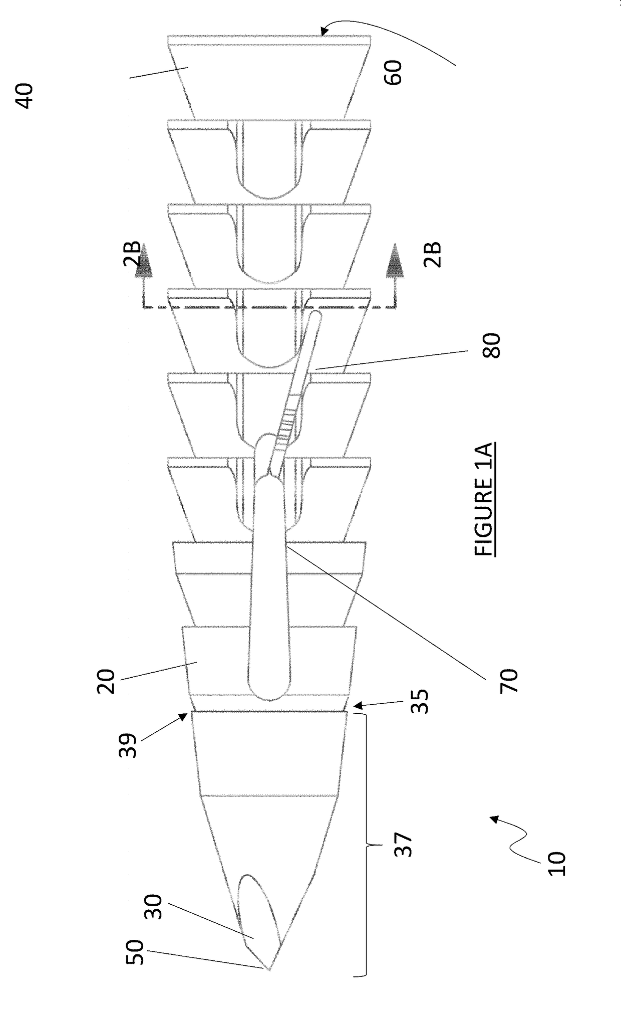
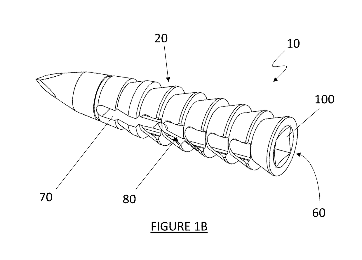
Disclosed are devices, methods and / or systems for securing tissue to bone, including a suture anchor implant having a body through which a suture eyelet extends transversely, and one or more suture pinch slits extending proximally from the suture eyelet, the suture pinch slit(s) angled relative to the longitudinal axis of the anchor such that a distal end of at least one suture pinch slit is positioned within a suture recess extending along the body and a proximal end of the at least one suture pinch slit is positioned outside of the suture recess.

Description

CROSS-REFERENCE TO RELATED APPLICATIONS[0001]This application claims the benefit of U.S. Provisional Patent Application Ser. No. 62 / 541,286 entitled “KNOTLESS ANCHOR,” filed Aug. 4, 2017, the disclosure of which is incorporated by reference herein in its entirety.TECHNICAL FIELD[0002]The invention relates to improved orthopedic tools and methods for use during orthopedic surgical procedures, including joint repair and / or replacement procedures. More specifically, disclosed are improved methods, apparatus and / or systems for securing and / or anchoring tissue structures to bones with a durable securement that facilitates accuracy and predictability of joint tension during joint surgery, including orthopedic repair of rotator cuff injuries.BACKGROUND OF THE INVENTION[0003]There are a wide variety of suture anchor designs, related devices and / or surgical techniques for securing sutures, which can be passed through soft tissue, to bone. Many of such designs rely on the interference between...

Claims


Application Information

Patent Timeline
Patent Type & Authority Applications(United States)
IPC IPC(8): A61B17/04A61F2/08
CPCA61B17/0401A61F2/0811A61B2017/0412A61B2017/0446A61F2002/0081A61F2002/0858A61F2002/0888A61F2220/0016A61F2230/0067A61B2017/0409A61B2017/0403A61B17/06166A61B2017/00473A61B2017/0453
Inventor CLARK, JEREMYSRIKUMARAN, UMASUTHANTHOMPSON, MATTHEW
Owner TIGON MEDICAL
Learn More