
Method of diagnosing a lubrication system of an engine

Active Publication Date: 2019-02-07
GM GLOBAL TECH OPERATIONS LLC
View PDF0 Cites 0 Cited by
  • Summary
  • Abstract
  • Description
  • Claims
  • Application Information

AI Technical Summary

Benefits of technology

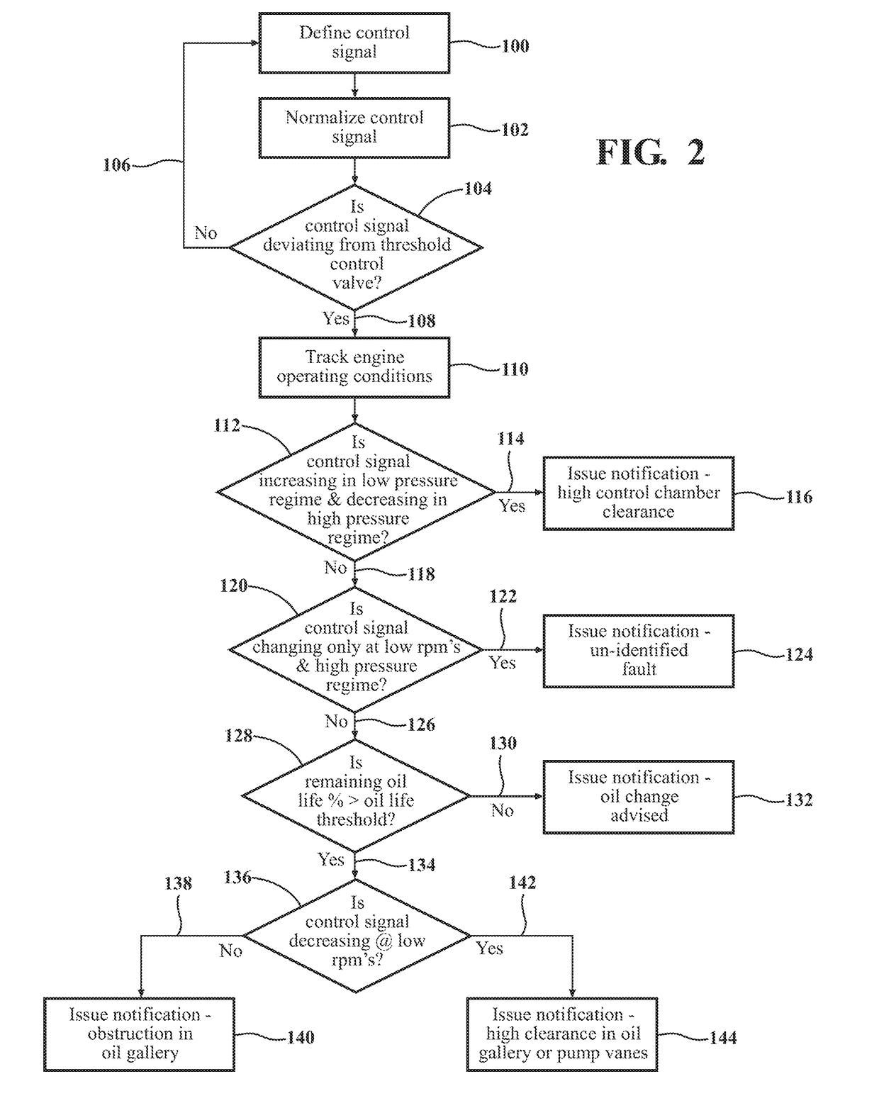
The patent is about a new method for diagnosing the lubrication system of an engine. The method analyzes the change in the value of the control signal used to control the oil pump for different operating conditions of the engine to identify different faults in the lubrication system. This new method improves the diagnostic capabilities of the processing unit and can help identify specific components of the lubrication system that may need service. The technical effect of this patent is to provide a more efficient and accurate way of diagnosing engine lubrication systems.

Problems solved by technology

Wear in the oil pump and / or the oil gallery, such as wear in the vanes of the oil pump, or wear between bearing surfaces or between piston rings and the cylinder bores, may affect the fluid pressure in the lubrication system.
Additionally, a blockage in the oil gallery may affect the fluid pressure in the lubrication system.
When the fault severity is greater than a severity threshold, the processing unit may issue a notification indicating excessive control chamber clearance in the oil pump.

Method used


Image

  • Method of diagnosing a lubrication system of an engine
  • Method of diagnosing a lubrication system of an engine

Examples


Embodiment Construction

[0018]Those having ordinary skill in the art will recognize that terms such as “above,”“below,”“upward,”“downward,”“top,”“bottom,” etc., are used descriptively for the figures, and do not represent limitations on the scope of the disclosure, as defined by the appended claims. Furthermore, the teachings may be described herein in terms of functional and / or logical block components and / or various processing steps. It should be realized that such block components may be comprised of a number of hardware, software, and / or firmware components configured to perform the specified functions.

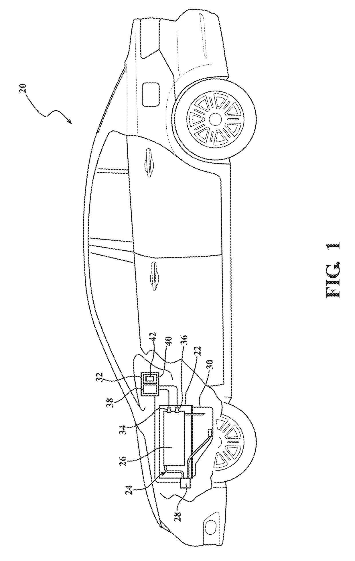
[0019]Referring to the FIGS., wherein like numerals indicate like parts throughout the several views, a vehicle is generally shown at 20 in FIG. 1. The vehicle 20 may include a type of moveable platform, including but not limited to a car, truck, a train, an ATV, a boat, a plane, etc.

[0020]Referring to FIG. 1, the vehicle 20 includes an engine 22. The engine 22 may include a type and / or configuration of ...


PUM


Abstract

A method of diagnosing a lubrication system of an engine includes controlling an oil pump with a control signal. The control signal is a command having a value for a desired lubrication fluid pressure from the oil pump for a current operating state of the engine. A processing unit compares the value of the control signal for the current operating state of the engine to a threshold control value for the current operating state of the engine. When the processing unit determines that the value of the control signal for the current operating state of the engine deviates from the threshold control value for the current operating state of the engine, the processing unit analyzes the value of the control signal to identify a fault in the lubrication system.

Description

INTRODUCTION[0001]The disclosure generally relates to a method of diagnosing a lubrication system of an engine.[0002]Engines include a lubrication system having an oil pump that circulates a lubrication fluid e.g., oil, through an oil gallery of the engine. As used herein, the term “oil gallery” includes not only the passages in the engine through which the lubrication fluid circulates, but also the surfaces between moving parts for which the lubrication fluid lubricates. Accordingly, the oil gallery includes bearing surfaces, piston rings, cylinder bores, passages, etc. The oil pump pressurizes the lubrication fluid to a desired lubrication fluid pressure, and circulates the lubrication fluid through the oil gallery. The desired lubrication fluid pressure may vary for different operating conditions of the engine, and should be maintained during engine operation.[0003]A vehicle controller is connected to the oil pump, and signals the oil pump with a control signal. The control signa...

Claims


Application Information

Patent Timeline
IPC IPC(8): F01M11/10F01M1/02
CPCF01M11/10F01M2011/142F01M2011/1446F01M1/02F01M1/16
Inventor SARWAR, AZEEMMEHDI, SYED B.LU, XIANGXINGPRYOR, BRYAN K.PEER, SHANSHAN L.
Owner GM GLOBAL TECH OPERATIONS LLC
Learn More