Hydraulic Drive System And Diagnostic Control Strategy For Improved Operation

Active Publication Date: 2010-08-26
WESTPORT FUEL SYST CANADA INC
View PDF1 Cites 7 Cited by
  • Summary
  • Abstract
  • Description
  • Claims
  • Application Information

AI Technical Summary

Benefits of technology

[0015]The method can further comprise stopping hydraulic fluid flow to the hydraulic drive unit when the calculated amount of mechanical work is less than the expected amount of mechanical work for a predetermined number of the drive cycles or if the calculated amount of mechanical work is less than the expected amount of mechanical work by a predetermined amount more than the predetermined margin. A small calculated amount of mechanical work can indicate that the storage vessel from which the process fluid is being pumped is empty or close to being empty, or that there is an equipment failure such as a broken drive shaft. The electronic controller can use the calculated amount of mechanical work in combination with other measured parameters to determine the cause of abnormal operating condition. For example, if the calculated amount of mechanical work is smaller than expected, and the process fluid pressure measured downstream from the pump discharge outlet is also below a low pressure threshold, and the end user of the process fluid is not consuming all of the process fluid that is being pumped to it, the electronic controller can determine that there is a leak in the process fluid system. Accordingly, this example shows that the control parameters corrected by the disclosed method can be used in combination with other control parameters to further refine the diagnostic capabilities and further improve operation of the hydraulic drive system and the machinery that it drives.
[0016]The method can be applied to a hydraulic drive system having a hydraulic drive unit that comprises a reciprocating hydraulic piston with a mechanically operable shuttle valve that automatically opens at the end of a hydraulic piston stroke to allow hydraulic fluid to flow from one side to the other side of the hydraulic piston. The method further comprises accurately determining the timing for the hydraulic piston completing its stroke, ending the drive cycle, and switching hydraulic fluid flow direction to begin a stroke of the hydraulic piston in an opposite direction, but determining when measured hydraulic fluid pressure decreases after the shuttle valve opens, a

Problems solved by technology

While this method works, a challenge associated with this approach is that peak hydraulic system pressure can change responsive to factors other than the amount of process fluid being pumped.
This is a problem for both single-acting and double-acting piston pumps, because a short stroke prevents the pump piston chamber from being fully charged with process fluid and/or from fully discharging the process fluid.
Conventional hydrau

Method used


Image

  • Hydraulic Drive System And Diagnostic Control Strategy For Improved Operation
  • Hydraulic Drive System And Diagnostic Control Strategy For Improved Operation
  • Hydraulic Drive System And Diagnostic Control Strategy For Improved Operation

Examples


Embodiment Construction

)

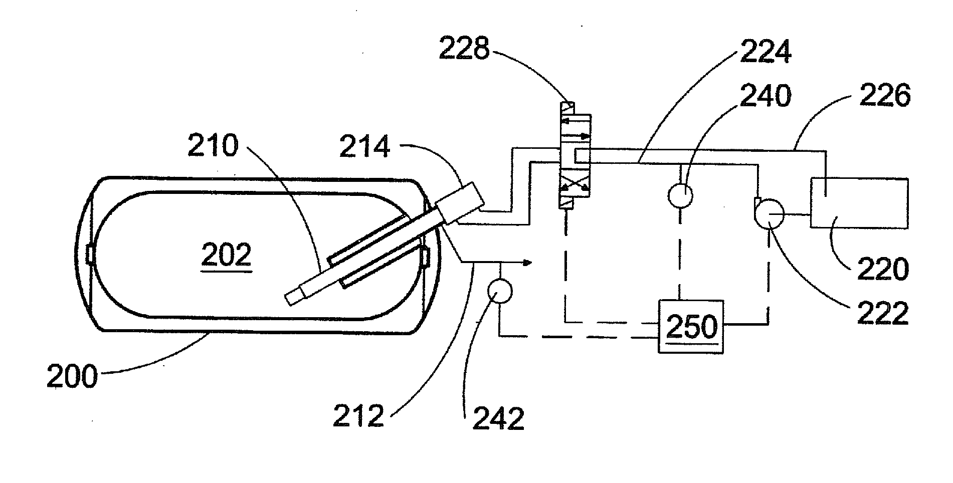
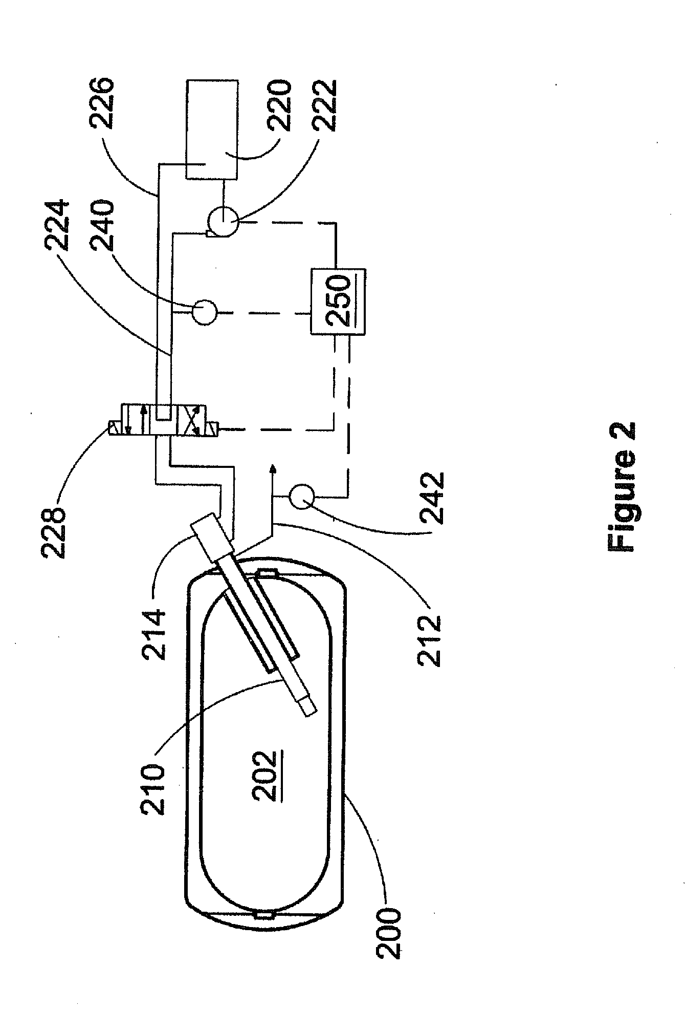
[0034]With reference to the figures, like-named components with like reference numbers separated by multiples of one hundred refer to like components and data in different embodiments and examples. Because a particularly useful application for the disclosed apparatus and method is pumping a liquefied gas stored at a cryogenic temperature from a cryogenic storage vessel, this example is used to describe the preferred embodiments illustrated by the figures. However, persons skilled in the technology will understand that the disclosed apparatus and method can be applied to pumping other process fluids that need not be stored at cryogenic temperatures, such as, for example, propane, and that it can also be applied to other applications that use a hydraulic drive system. The method and apparatus is particularly useful if there is variable resistance from the driven machinery, and / or, if the hydraulic pump is driven at a variable speed.

[0035]FIGS. 2-4 illustrate schematic views of differ...


PUM


Abstract

A method and apparatus are provided for hydraulic fluid supply between a hydraulic pump and a hydraulic drive unit, switching hydraulic fluid flow direction to the hydraulic drive unit or stopping hydraulic fluid flow to the hydraulic drive unit when measured hydraulic fluid pressure crosses a predetermined pressure threshold value. The method further comprises calculating an amount of mechanical work done by the hydraulic drive unit and warning an operator or limiting hydraulic fluid flow rate to the hydraulic drive unit when the calculated mechanical work for the drive cycle is less than an expected amount of mechanical work. The apparatus for practicing the method further includes a pressure sensor associated with a hydraulic fluid supply conduit between the pump and the drive unit, and an electronic controller programmed to operate the drive system according to the method.

Description

CROSS-REFERENCE TO RELATED APPLICATION(S)[0001]This application is a continuation of International Application No. PCT / CA2008 / 001772, having an international filing date of Oct. 3, 2008, entitled “Hydraulic Drive System And Diagnostic Control Strategy For Improved Operation”. The '772 international application claimed priority benefits, in turn, from Canadian Patent Application No. 2,602,164 filed Oct. 4, 2007. The '772 international application is hereby incorporated by reference herein in its entirety.FIELD OF THE INVENTION[0002]The present invention relates to a hydraulic drive system and a diagnostic control strategy for improved operation. While many hydraulic drive-systems can benefit from the disclosed system and control strategy, it is particularly advantageous for systems that use a hydraulic fluid pump that is operated at different speeds, for example, such systems that have a hydraulic fluid pump that is mechanically driven by an engine, wherein hydraulic pump speed is pr...

Claims


Application Information

Patent Timeline
IPC IPC(8): F15B20/00F15B11/08
CPCF15B11/08F15B21/08F15B2211/633F15B2211/6309F15B2211/327
Inventor BATENBURG, GREG
Owner WESTPORT FUEL SYST CANADA INC
Why Eureka
Try Eureka