Method for diagnosing an internal combustion engine in a motor vehicle

a technology for internal combustion engines and motor vehicles, applied in the direction of electrical control, instruments, nuclear elements, etc., can solve the problems of output error associated with reference spectrum, additional vibration, and additional airborne or structure-borne noise of a certain frequency, and achieve the effect of expanding the diagnostic capabilities of components

Inactive Publication Date: 2008-06-12
ROBERT BOSCH GMBH
View PDF26 Cites 24 Cited by
  • Summary
  • Abstract
  • Description
  • Claims
  • Application Information

AI Technical Summary

Benefits of technology

[0003]An object of the present invention is to extend the diagnostic capabilities of components of the motor vehicle, in particular of the internal combustion engine and its components.

Problems solved by technology

Certain types of interference, errors, or defects of an internal combustion engine or associated units generate additional vibrations and thus additional airborne or structure-borne noise of a certain frequency.
If a sound spectrum at a certain frequency recorded by a sensor unit or the receiver of the sensor unit exceeds a maximum amplitude, this indicates a certain associated error.
Similarly, when a maximum value of a cross-correlation between frequency spectrum and reference spectrum is exceeded, an error associated with the reference spectrum is output.

Method used


Image

  • Method for diagnosing an internal combustion engine in a motor vehicle
  • Method for diagnosing an internal combustion engine in a motor vehicle

Examples


Embodiment Construction

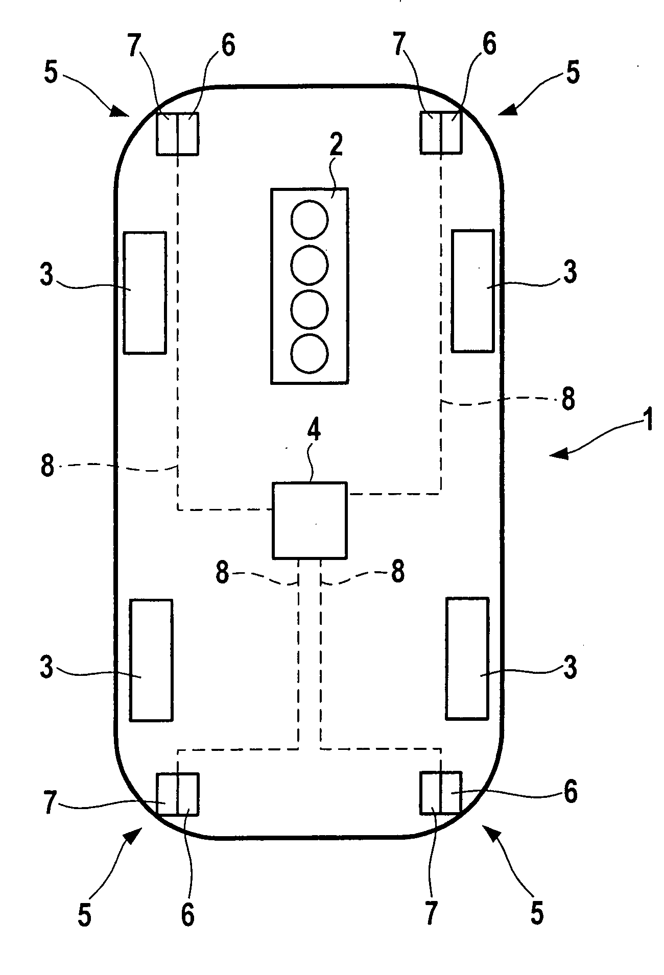
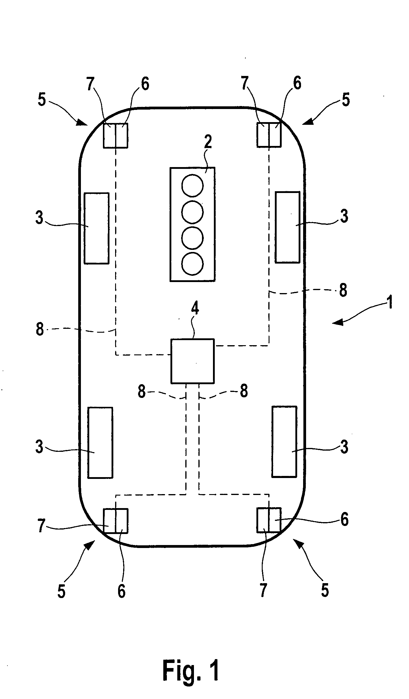
[0010]FIG. 1 schematically shows a motor vehicle 1 having an internal combustion engine 2, which may be a gasoline engine, a diesel engine, a Wankel engine, or the like, and a transmission, which is not shown in detail, for example, a manual transmission, which is connected to the internal combustion engine via a clutch, or an automatic transmission, the transmission driving driving wheels 3. Motor vehicle 1 includes a control unit 4, which controls all functions, including those of the internal combustion engine. Control unit 4 may be subdivided into individual control units for different functions; there may be, for example, a control unit for the internal combustion engine itself, and a control unit for controlling functions in the passenger compartment and for acoustic and visual outputs, as well as for receiving operating inputs. The motor vehicle includes a plurality of sensor units 5, each of which includes a sound transmitter 6 and a sound receiver 7. Sound transmitter(s) 6 ...


PUM


Abstract

A method for diagnosing an internal combustion engine in a motor vehicle having at least one sensor unit, including at least one sound receiver, the sound receiver converting sound waves into an electrical signal. Sound waves of the internal combustion engine are recorded using the sound receiver of the sensor unit and converted into an electrical signal, and the electrical signal is used for the diagnosis of the operating state of the internal combustion engine.

Description

FIELD OF THE INVENTION[0001]The present invention relates to a method for diagnosing an internal combustion engine in a motor vehicle having at least one sensor unit which includes a sound transmitter and a sound receiver, the sound receiver converting sound waves into an electrical signal. The present invention furthermore relates to a device, in particular a control unit, which is designed for carrying out the method, and a computer program having program code for carrying out all steps of such a method.BACKGROUND INFORMATION[0002]In older motor vehicle models, the driver has the possibility of drawing conclusions regarding possible problems or errors or damage on the basis of the perceived engine noise. For example, a whistling sound of a V-belt may be perceived and a possible error, for example an insufficient tension of the V-belt, may be deduced therefrom. The knocking of a turbocharger may be perceived, etc. Noise insulation in the engine compartment and in the passenger comp...

Claims


Application Information

Patent Timeline
Patent Type & Authority Applications(United States)
IPC IPC(8): G01M15/12G06F15/00
CPCF02D41/22Y02T10/40F02D2200/025F02D2041/288
Inventor SCHNEIDER, MARCUSBECKER, MARKUSSCHEUERLE, THOMAS
Owner ROBERT BOSCH GMBH
Why Eureka
Try Eureka