
System, method and apparatus for modular, mobile rail fueling

a technology of modular fueling and mobile rail, applied in the field of fueling vehicles, can solve the problems of increasing lng use, requiring significant capital investment, and not being readily available in most parts of the country

Active Publication Date: 2019-02-07
BNSF RAILWAY
View PDF19 Cites 8 Cited by
  • Summary
  • Abstract
  • Description
  • Claims
  • Application Information

AI Technical Summary

Benefits of technology

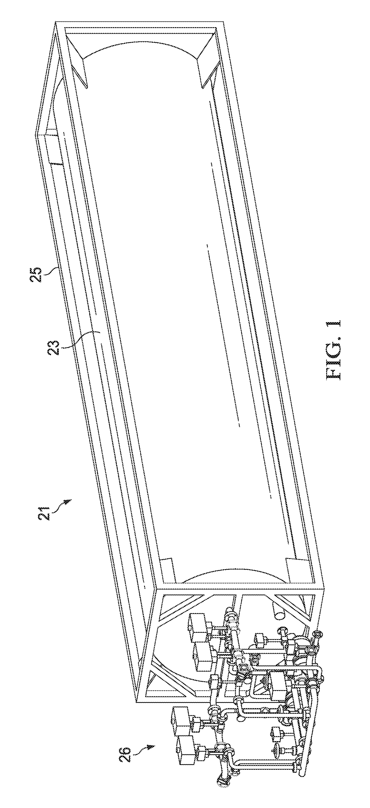
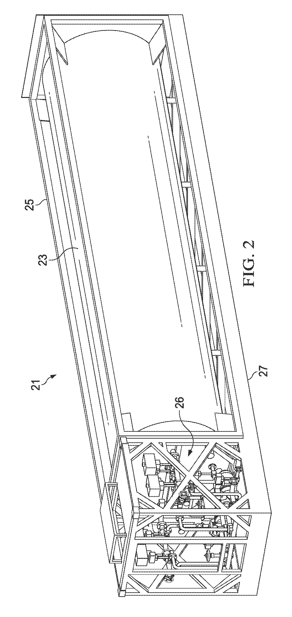
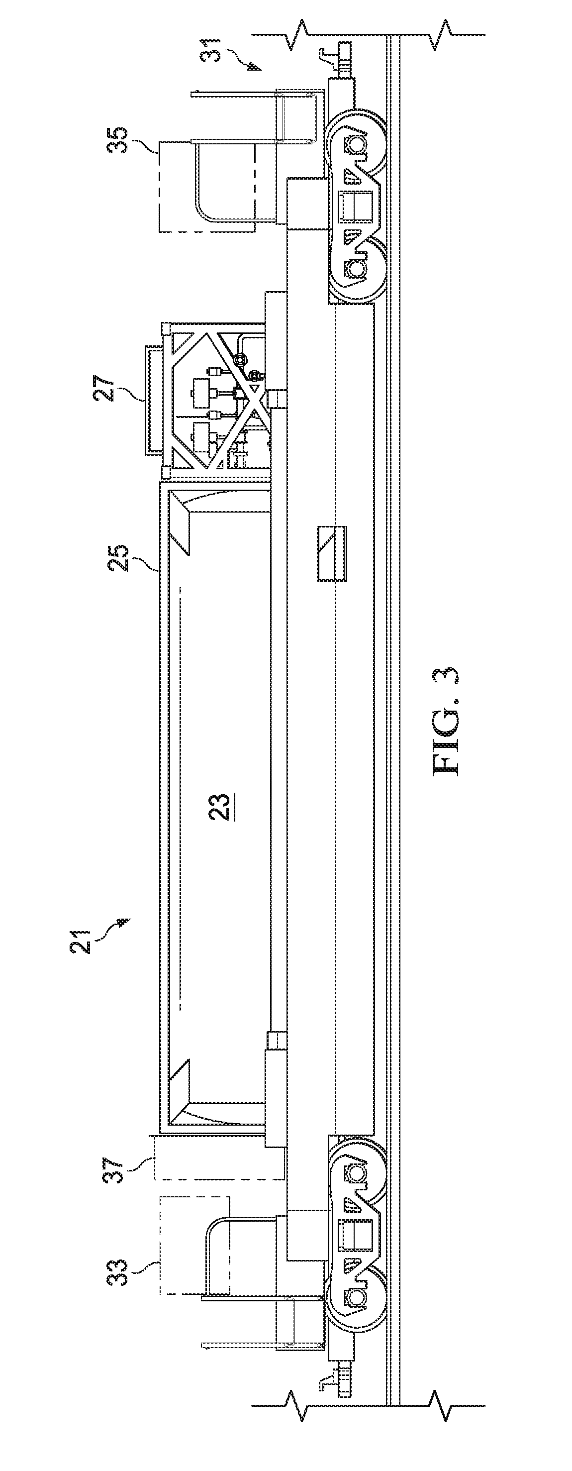
This patent describes a system for modular, mobile rail fueling using intermodal rail cars. The system includes a platform with a cryogenic storage tank for LNG fuel, which can be delivered to one or more LNG storage vessels on the intermodal rail car. The intermodal well rail car provides power, storage, lighting, and compressed air to the platform. The method involves mounting the portable platform to the intermodal rail car's footprint, delivering LNG fuel to the storage vessels, and providing additional needs like power and lighting to the platform. The technical effects include increased flexibility and efficiency in LNG fueling for rail cars.

Problems solved by technology

Current industry offerings do not address the needs of growing LNG use in the rail industry.
Railroad fueling infrastructure, and specifically LNG fueling infrastructure, requires significant capital investment.
LNG is presently an alternative fuel, not having been adopted in widespread use for rail applications, and is not readily available in most parts of the country.
Specific issues to further adoption of LNG for rail use include weight restrictions for on-road transports require multiple deliveries of LNG to fuel single LNG locomotives or LNG fuel tenders.
In addition, the inaccuracy of level detection systems means some LNG is “backhauled” by on-road transports if the tender has more LNG onboard than reported.
Transports typically do not have the power or pump capacity to fill at flow rates near those of current diesel “fuel pad” flow rates.
Moreover, there are no automatic refueling controls for rail vehicles on the market, so LNG refueling requires technically skilled labor to complete refueling operations.
Construction of fixed refueling infrastructure requires large capital expense and is incapable of being repositioned if market conditions change.
Given the large potential impact to railroad operations, existing fueling locations may not be ideal for LNG.

Method used


Image

  • System, method and apparatus for modular, mobile rail fueling
  • System, method and apparatus for modular, mobile rail fueling
  • System, method and apparatus for modular, mobile rail fueling

Examples


embodiment 1

[0047] A system for portable, modular fueling, the system comprising:

[0048]a platform configured for intermodal rail transport, the platform having a storage tank for fuel and mounted to a frame, and the storage tank is configured to be in fluid communication with one or more storage vessels for fuel to deliver fuel thereto.

embodiment 2

[0049] The system of any of these embodiments, wherein the system is configured to handle fuel in both a gaseous state and a liquid state.

embodiment 3

[0050] The system of any of these embodiments, wherein the platform is configured to be mounted to an intermodal well rail car capable of providing a modular, on-board dispensing system, power, storage, lighting and compressed air.


PUM


Abstract

A portable, modular fueling system for the storage, dispensing and offloading of fuel from a rail vehicle to one or more other fuel storage vessels is disclosed. The system module is self-contained on an ISO standardized intermodal platform. The module is capable of being in fluid communication with a plurality of modular storage vessels, either rail-bound or wayside, such as for delivering fuel to a fuel tender or a locomotive. Electrical power, equipment storage, lighting, and compressed air may be located on the intermodal rail car or in a support module, such as either ground-based or rail-mobile. Alternatively, the platform can be mounted to a trailer chassis, or affixed to a land-based foundation matching the standardized intermodal container footprint. Control of the fuel system is provided by automatic means with manual override.

Description

BACKGROUND OF THE INVENTIONField of the Disclosure[0001]The present invention relates in general to fueling vehicles and, in particular, to a system, method and apparatus for modular, mobile rail fueling.Description of the Prior Art[0002]Liquid natural gas (LNG) refueling technology is well established for road vehicles and marine vessels. Numerous vendors provide equipment for mobile refueling from a road-going transport, stationary fueling in a service area or dock / port. Current refueling of LNG rail vehicles is performed from on-road transports either through differential pressure transfer or pump transfer. Widespread use of LNG as a fuel in the rail industry requires a mixture of fixed fueling facilities and mobile refueling from on-road transports. Current industry offerings do not address the needs of growing LNG use in the rail industry.[0003]Railroad fueling infrastructure, and specifically LNG fueling infrastructure, requires significant capital investment. LNG is presently...

Claims


Application Information

Patent Timeline
Patent Type & Authority Applications(United States)
IPC IPC(8): F17C6/00F17C7/02F17C13/00F17C13/04F17C13/08
CPCF17C6/00F17C2250/03F17C13/005F17C13/04F17C13/083F17C2223/033F17C2250/01F17C2221/033F17C2225/0161F17C2203/0391F17C2225/033F17C2270/0173F17C2223/0161F17C2265/065F17C2201/019F17C2227/0341F17C7/02F17C9/00F17C2201/0104F17C2201/035F17C2201/054F17C2205/0107F17C2205/0126F17C2205/0157F17C2205/0323F17C2221/012F17C2221/035F17C2223/0123F17C2223/0153F17C2223/035F17C2225/044F17C2270/0168Y02E60/32
Inventor KRUEGER, DARRELLSOLES, JOSHUA
Owner BNSF RAILWAY
Learn More