Low-cost, high-performance radar networks

a radar network and low-cost technology, applied in the field of land-based radar surveillance, can solve the problems of insufficient tracking circuits included with these radars, mediocre radar performance, and further complicating matters, so as to improve tracking performance, improve tracking quality, and improve the effect of human effor

Active Publication Date: 2011-05-10
ACCIPITER RADAR TECH
View PDF16 Cites 48 Cited by
  • Summary
  • Abstract
  • Description
  • Claims
  • Application Information

AI Technical Summary

Benefits of technology

[0018]A primary object of the present invention is to provide a land-based, radar system that is low-cost and high-performance for Homeland Security, BASH and NRM applications.
[0038]Further human cost reductions can be achieved with the present invention through the provision of hardware and software to remotely control the operation of each radar sensor, including the operation of each sensor's radar processor, as well as the operation of its marine radar transceiver. A novel feature of the present invention is the remote control of each radar sensor to reduce the human cost of operating and maintaining the radar network of radar sensors.

Problems solved by technology

However, in operation (for homeland security and avian radar applications) these radars deliver mediocre performance because of their primitive signal processing.
The presence of many friendly targets further complicates matters and the tracking circuits included with these radars are completely inadequate for our targets of interest.
This is a difficult task that causes operator fatigue very quickly, is not reliable, and hence is not used in practice.
These prior art systems exploit the fact that the radars are mounted on vessels and that sea clutter decorrelates over a relatively short time.
The consequence of using lower detection thresholds is that an undesired, higher false alarm rate results, particularly due to the strong clutter residual in the vicinity of the land-based radars used in the present invention.

Method used


Image

  • Low-cost, high-performance radar networks
  • Low-cost, high-performance radar networks
  • Low-cost, high-performance radar networks

Examples


Embodiment Construction

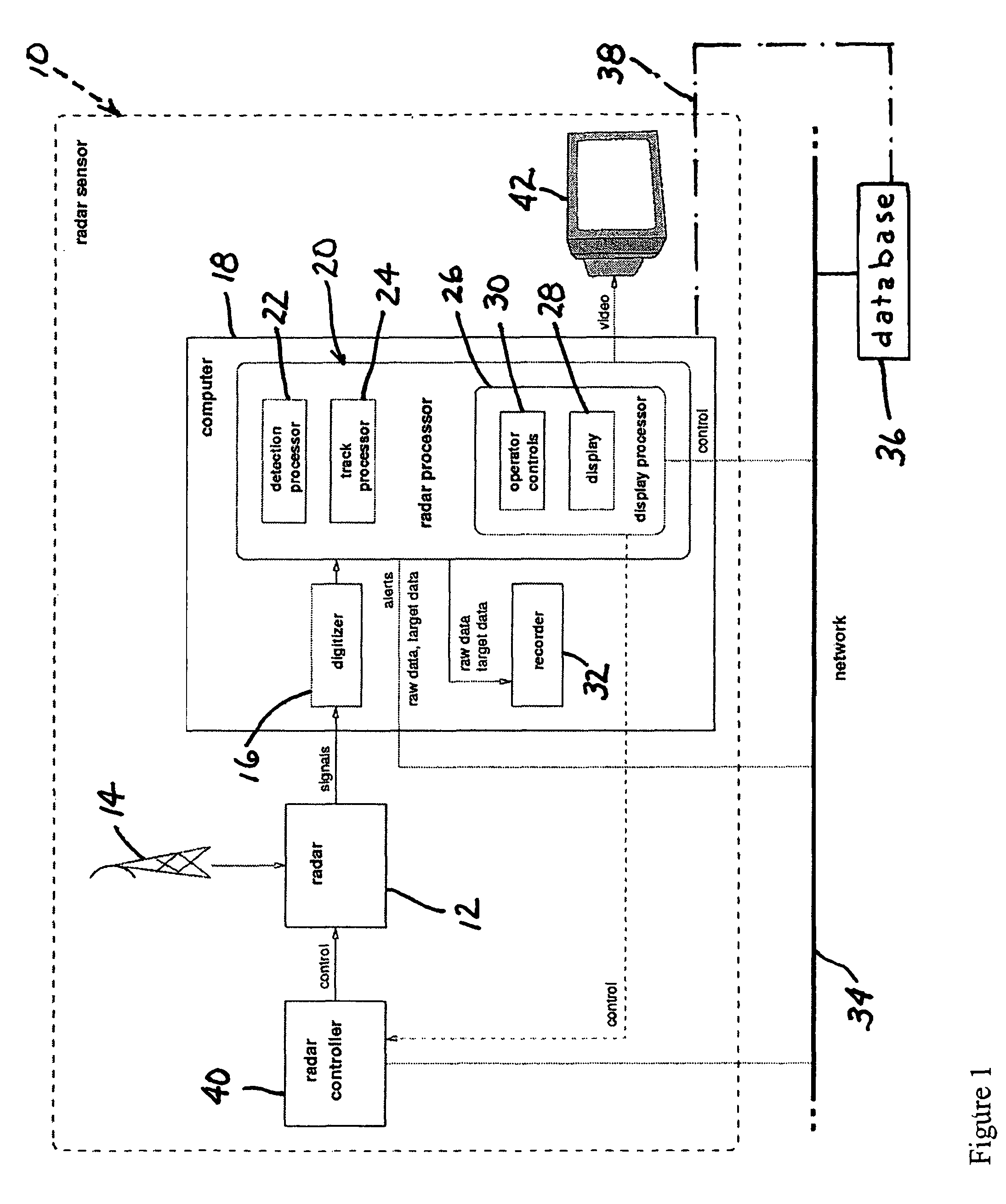
[0046]A block diagram of a radar sensor apparatus 10 in accordance with the present invention is shown in FIG. 1. Characteristics of each block are as follows. The radar sensor apparatus 10 includes a radar device 12 that is typically noncoherent and transmits pulses of constant width at a constant pulse repetition frequency (PRF) at X-band or S-Band. Radar device 12 typically has either a continuously rotating or sector scanning antenna 14. Antenna 14 is elevated to be several meters above the area to be monitored, and has a detection range of several kilometers. COTS marine radars typically have these characteristics and are preferred for the present invention due to their availability, low-cost, and good antenna and transceiver characteristics. Radar device 12 takes the form of a marine radar, which utilizes a waveform in the microwave portion of the electromagnetic spectrum. A typical marine radar is noncoherent, transmits at X-band with 50 kW peak power, pulse repetition freque...


PUM


Abstract

A real-time radar surveillance system comprises at least one land-based non-coherent radar sensor apparatus adapted for detecting maneuvering targets and targets of small or low radar cross-section. The radar sensor apparatus includes a marine radar device, a digitizer connected to the marine radar device for receiving therefrom samples of radar video echo signals, and computer programmed to implement a software-configurable radar processor generating target data including detection data and track data, the computer being connectable to a computer network including a database. The processor is figured to transmit at least a portion of the target data over the network to the database, the database being accessible via the network by at least one user application that receives target data from the database, the user application providing a user interface for at least one user of the system.

Description

FIELD OF THE INVENTION[0001]This invention relates to land-based radar surveillance of wide areas or local sites. It also relates to radar detection and tracking and multi-sensor fusion.BACKGROUND OF THE INVENTION[0002]“Homeland Security” refers to the goal of detecting and defending against threats to public safety posed by potential attack by hostile individuals or groups. Homeland Security applications for radar surveillance differ fundamentally from most military applications. The high price of military radars is justified by the critical and urgent need for protection in combat zones or near high-value assets. The price is affordable because the deployments are confined in time and / or space. Homeland Security, in contrast, deals with threats, such as terrorist attacks, that materialize infrequently and can occur anywhere. Surveillance to counter such threats must be deployed simultaneously across huge areas on a permanent 24 / 7 basis. Therefore, in the market for sensors used fo...

Claims


Application Information

Patent Timeline
Patent Type & Authority Patents(United States)
IPC IPC(8): G01S13/93G01S13/937
CPCG01S7/003G01S7/22G01S7/292G01S13/87G01S7/068G01S13/726G01S7/046G01S13/937G01S13/917
Inventor NOHARA, TIMOTHY J.PREMJI, AL-NASIRUKRAINEC, ANDREW M.WEBER, PETER TJONES, GRAEME S.KRASNOR, CARL E.
Owner ACCIPITER RADAR TECH
Why Eureka
Try Eureka