Hydro-electric farms

a hydroelectric farm and ocean current technology, applied in the direction of electric generator control, machines/engines, mechanical equipment, etc., can solve the problems of limited heat in air-based generators, achieve the effect of increasing the generated heat dispersion, and reducing the cost of electricity generation

Inactive Publication Date: 2006-01-03
HYDRO ELECTRIC FARMS
View PDF132 Cites 49 Cited by
  • Summary
  • Abstract
  • Description
  • Claims
  • Application Information

AI Technical Summary

Benefits of technology

[0005]The exterior and interior surfaces of this new generator is coated with a new combination of composite layers to form a non-conductive, heat dissipating, anti-fouling, caustic water environment specific, protective coating thus allowing the entire apparatus sustained immersion in the ocean water.
[0006]These generators are designed to allow the ocean current to pass through their shapes to further aid in heat dissipation. Air based generators are limited by heat in the amount of electrical current they produce. In this invention, by allowing the water to flow around the windings and increase the generated heat dispersion, it can produce larger amounts of electric current from the same size generator with industry standard windings.
[0007]These electrical generators could also incorporate the use of a brush-less design, whereas the rotator components are never actually in contact with the stator assembly. The extended life of each unit and each individual component is one of the overall design goals of this invention.
[0010]Placement of the electric generators minimizes environmental and boat traffic concerns. Other placement criteria include: a) degree of slope of the bottom which could be anywhere between vertical and horizontal, b) actual composition of the bottom, c) placement proximity to final use of the generated electricity, d) location of optimum constant ocean current.

Problems solved by technology

Air based generators are limited by heat in the amount of electrical current they produce.

Method used


Image

  • Hydro-electric farms
  • Hydro-electric farms
  • Hydro-electric farms

Examples


Embodiment Construction

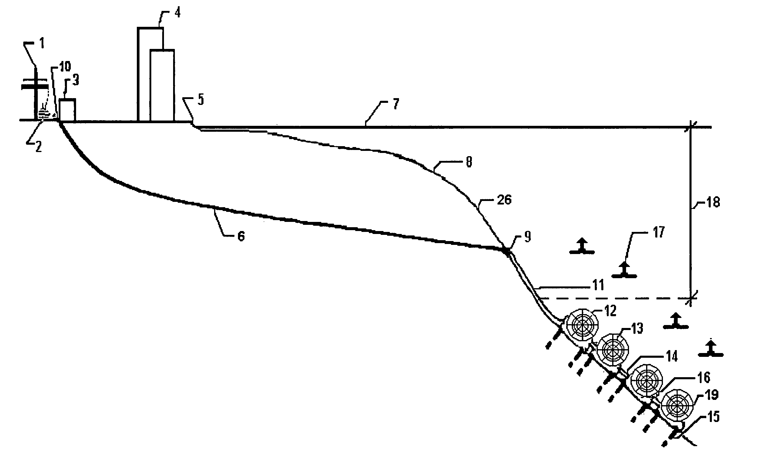
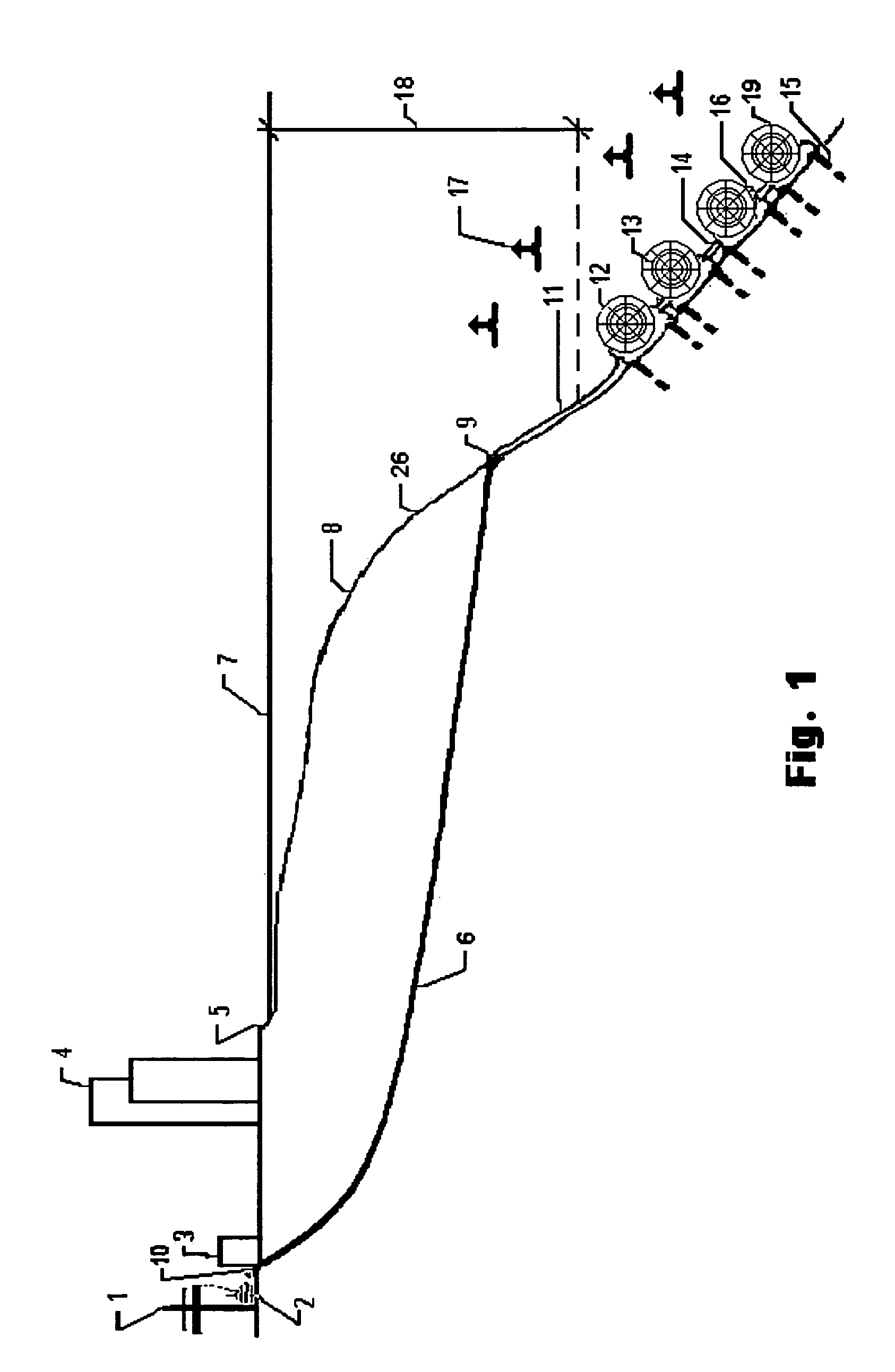
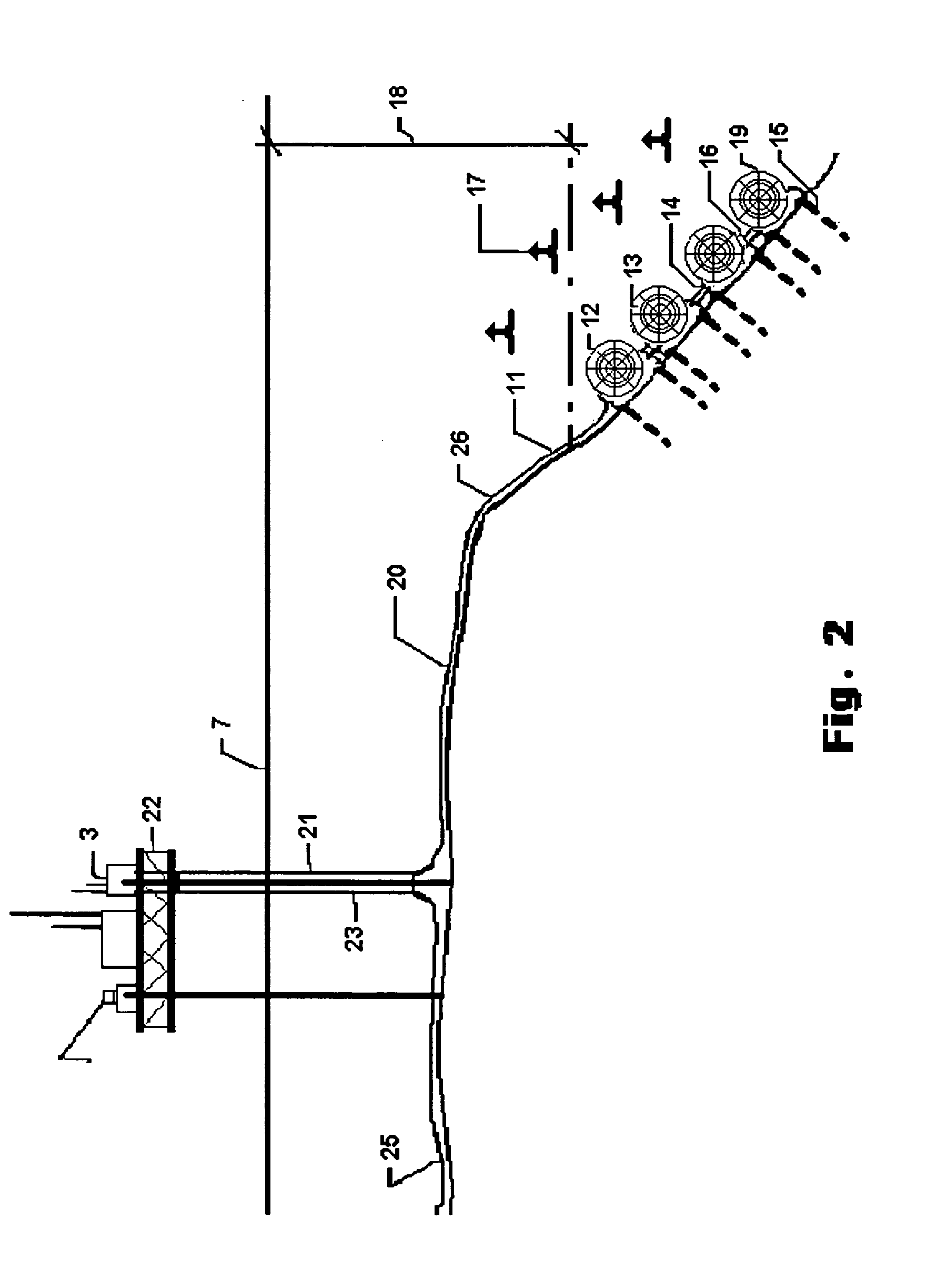
[0052]FIG. 1: Cross Section View of an Adjacent Site Hydro-Electric Farm. Shown in this view is the direct immersion type of electrical generator 12. The exterior and interior surfaces of this generator is coated with a protective covering 19. Also shown are the composite turbine blade / propellers 13, the ocean current 17, pre-assembled cradle 16 and the pile type devices 15. This anchoring system can be used either horizontally into the side of the underwater channel drop-offs 8 or vertically into the bottom of the current channels 26. The layout of the multiple generators is based on current flow 17 and the required design minimum depth 18 for the generator assemblies 12 / 13, from the ocean surface 7.

[0053]The power transmission lines to the mainland are via under water transmission cables 11 that are pulled thru the directional drilled conduits 6. Close to the mainland, these transmission lines are routed through the entrances 9 of the conduits 6, to sites set well back from the co...


PUM


Abstract

An underwater hydro-electric farm comprising a plurality of electrical generator assemblies arranged in an array on a bottom surface of a body of water within an ocean current path to take generate power from a kinetic energy caused by the flow of the underwater current. Each assembly is installed in a cradle, which is anchored with a pile driven system to the bottom surface. Each assembly is a modular system allowing for easy swapping out of an assembly under water. Generated power is transmitted to a land based facility directly to or through an intermediate transfer station. Generator portion may have internally or externally supported field windings. Various configurations of propellers may be used, some with channels or solid vanes and another being a spiral shaped propeller. All water exposed surfaces of the generator and propeller portions are coated with a non-conductive, heat dissipating, anti-fouling and water specific protective coating.

Description

[0001]This application claims the benefit of provisional application No. 60 / 458,488, filed Mar. 28, 2003.FIELD OF THE INVENTION[0002]The invention is related to underwater ocean current Hydro-Electric farms and the electrical generators used for such farms.BACKGROUND OF THE INVENTION[0003]The problem with underwater ocean current flow power conversion to electric energy up to now has been that the electric generators had to be shielded from the ocean water, either by placing them above the surface of the water or enclosing them in watertight containers.SUMMARY OF THE INVENTION[0004]What is needed is a new and unique invention that can use a direct ocean water immersion type of electrical generator. These generators can incorporate either an internal framework with the stator wire coils attached to and wound around this framework, which can then support this new assembly, or the more conventional exterior supported coil wire arrangement, sometimes known as the clamshell type arrangem...

Claims


Application Information

Patent Timeline
Patent Type & Authority Patents(United States)
IPC IPC(8): F03B13/10F03B17/06
CPCF03B17/06E02B2017/0091Y02E10/28F05B2240/97F05B2240/40Y02E10/30Y02E10/20
Inventor THARP, JOHN E.
Owner HYDRO ELECTRIC FARMS
Why Eureka
Try Eureka