Near eye display system and operation method thereof

Active Publication Date: 2019-02-07
WISTRON CORP
View PDF20 Cites 12 Cited by
  • Summary
  • Abstract
  • Description
  • Claims
  • Application Information

AI Technical Summary

Benefits of technology

[0005]The invention provides near eye display syst

Problems solved by technology

As a result, the same image focused by the sight centers of the left-eye and the right-eye of the user will not be at the correct positions, and thus it is difficult for the eyes to focus.
The problems above will have a negative impact on

Method used


Image

  • Near eye display system and operation method thereof
  • Near eye display system and operation method thereof
  • Near eye display system and operation method thereof

Examples


Example

[0024]Reference will now be made in detail to the present preferred embodiments of the invention, examples of which are illustrated in the accompanying drawings. Wherever possible, the same reference numbers are used in the drawings and the description to refer to the same or like parts.

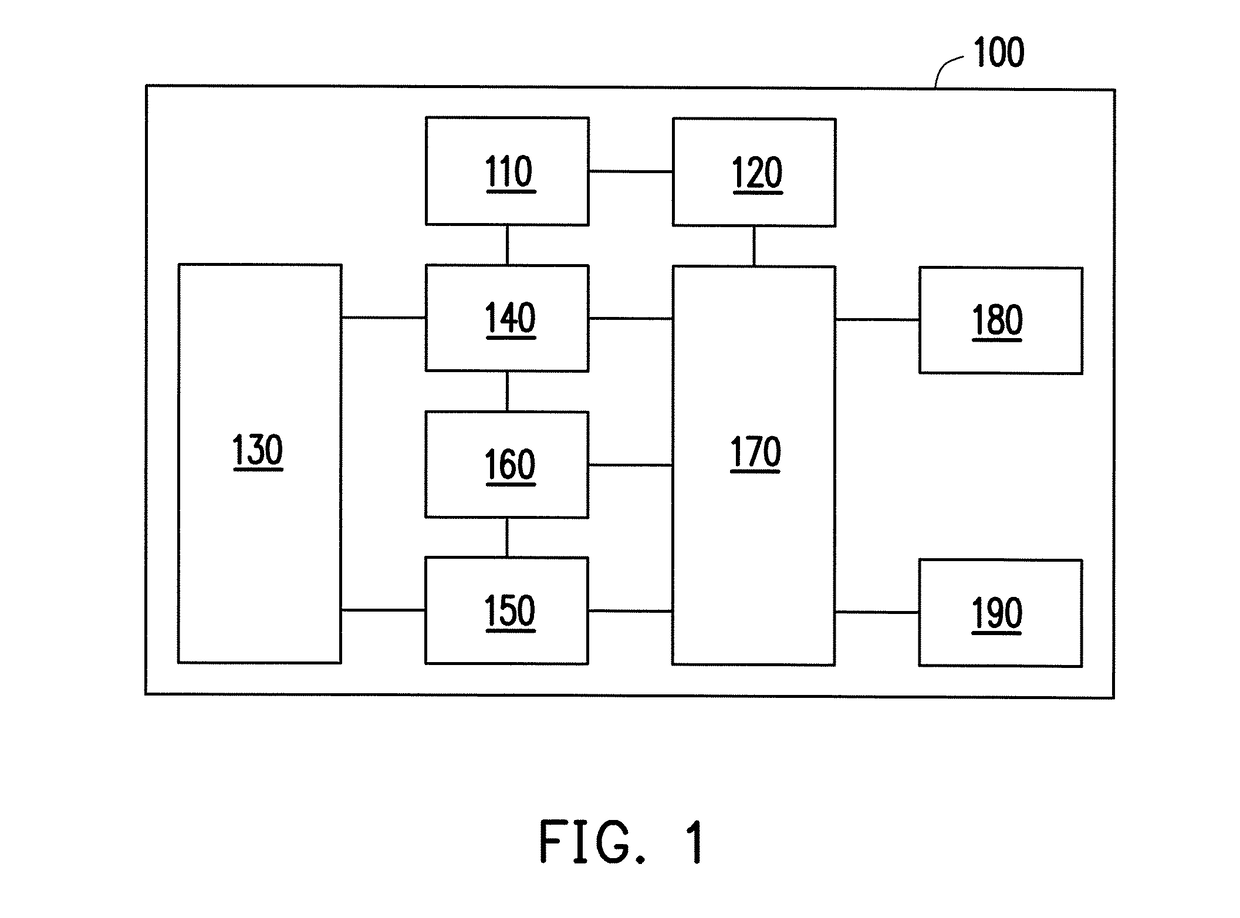
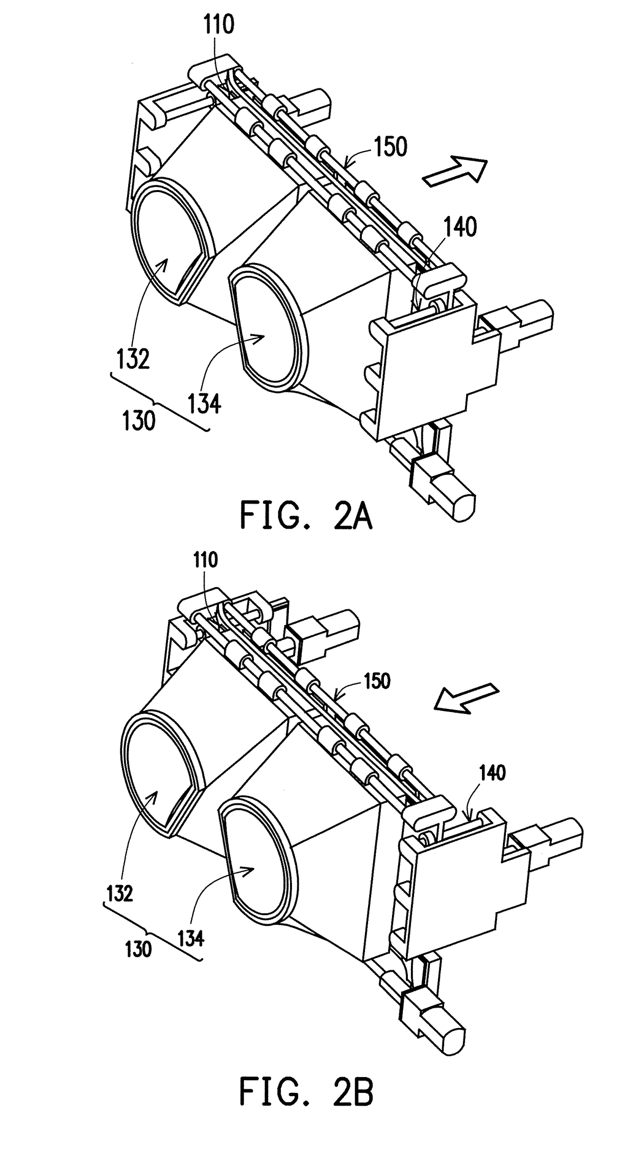
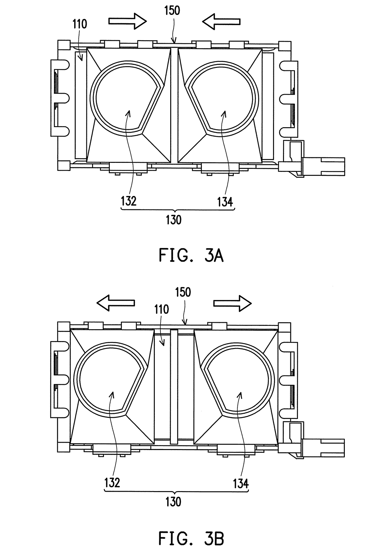
[0025]FIG. 1 is a block diagram of a near eye display system according to an embodiment of the invention. FIG. 2A and FIG. 2B are schematic views of a near eye display system in a longitudinal movement (a front-back movement) according to an embodiment of the invention. FIG. 3A and FIG. 3B are schematic views of a near eye display system in a lateral movement (a left-right movement) according to an embodiment of the invention. FIG. 4A to FIG. 4C are schematic diagrams for adjusting a center of a left-eye image and a center of a right-eye image according to an interpupillary distance. FIG. 5 is a flowchart of an operation method of a near eye display system according to an embodiment of the invention....


PUM


Abstract

A near eye display system including a display screen, a graphic processing unit, a lens group, a focal length adjustment device, an interpupillary distance adjustment device, a detection unit, and a control unit is provided. Positions of a left-eye image and a right-eye image to be displayed on the display screen may be adjusted based on lateral displacement amounts of a left-eye lens and a right-eye lens, such that centers of the left-eye image and the right-eye image are respectively aligned with centers of the left-eye lens and the right-eye lens. Sizes (magnification) of the left-eye image and the right-eye image to be displayed on the display screen may be adjusted based on longitudinal displacement amounts of the left-eye lens and the right-eye lens, such that sizes of a visual left-eye image and a visual right-eye image seen by a user are identical. Operation methods thereof are also provided.

Description

CROSS-REFERENCE TO RELATED APPLICATION[0001]This application claims the priority benefit of Taiwan application serial no. 106125974, filed on Aug. 1, 2017. The entirety of the above-mentioned patent application is hereby incorporated by reference herein and made a part of this specification.BACKGROUND OF THE INVENTION1. Field of the Invention[0002]The invention relates to display systems and operation methods thereof, and more particularly, to near eye display systems and operation methods thereof.2. Description of Related Art[0003]On the market, a near eye display used in Virtual Reality (VR) applications generally includes lenses and a display screen. The lenses are disposed between human eyes and the display screen, and the display screen is disposed within focuses of the lenses, so that images on the display screen can pass through the lenses and be formed into erected magnified virtual images at the back of the display screen. Since different users may have different interpupil...

Claims


Application Information

Patent Timeline
IPC IPC(8): G02B27/01G06T3/40
CPCG02B27/0172G06T3/40G02B2027/0134G02B2027/014G02B2027/0141G02B2027/0132G02B2027/0154H04N13/344H04N2213/001H04N2213/002H04N13/327H04N13/398H04N13/122G02B27/0176G02B7/12
Inventor CHANG, YAO-TSUNGLIANG, CHEN-YI
Owner WISTRON CORP
Why Eureka
Try Eureka