
Dynamically Balanced Multi-Degrees-of-Freedom Hand Controller

a hand controller and degree of freedom technology, applied in the field of control systems, can solve the problems of noisy output of an imu for rotation about the z-axis corresponding to the yaw of the first control member, is difficult to measure, and is not mobil

Active Publication Date: 2019-02-07
FLUIDITY TECH INC
View PDF31 Cites 26 Cited by
  • Summary
  • Abstract
  • Description
  • Claims
  • Application Information

AI Technical Summary

Benefits of technology

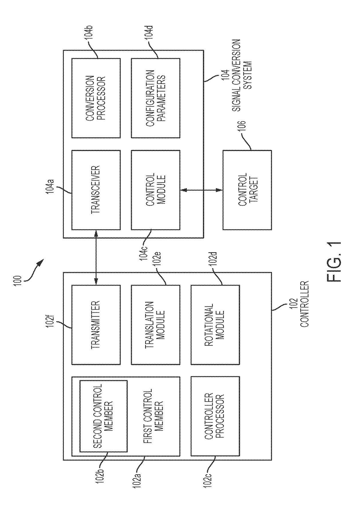
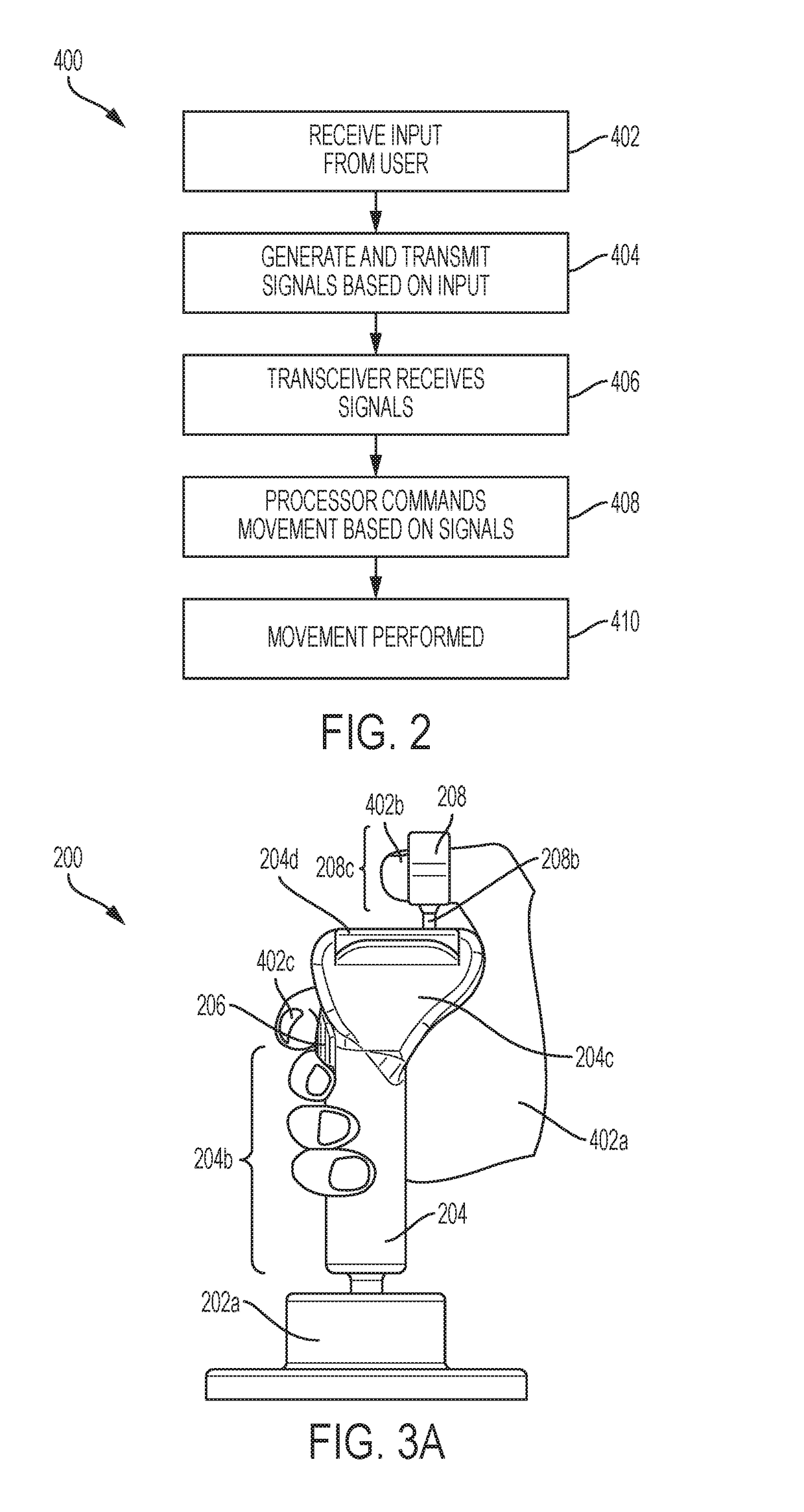
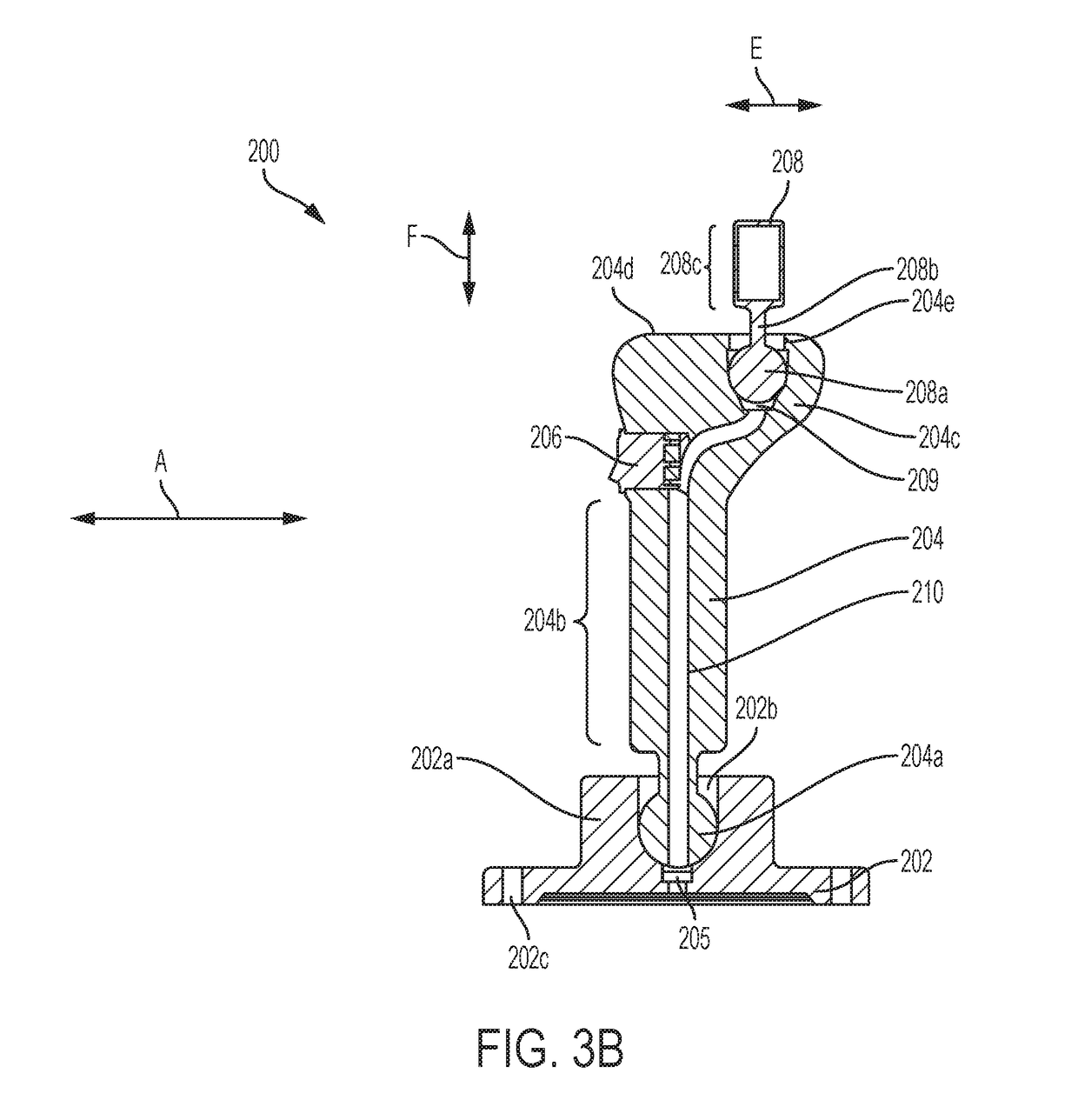
The patent describes a single-handed controller that improves gaming and motion control for computer augmented reality and virtual reality users. The controller allows for precise movements in three dimensions simultaneously and limits unintended motions. It also includes a thumb-less second member and a third control member for displacement by one or more digits of the user's single hand. The controller mounts on the wrist and registers displacement from a neutral position, allowing for intuitive movements like a pilot in virtual or augmented reality. Additionally, the patent describes a two-handed controller that stabilizes the base while also allowing for pitch, yaw, and roll inputs with tactile feedback.

Problems solved by technology

They are also typically not mobile.
Extended operation of a controller with a second member with a thumb for independent control inputs, particularly when the second member is pulled up or pushed down by the thumb, might lead to fatigue.
Yaw is difficult to measure with an inertial measurement unit (IMU) within a hand-held controller.
For example, although an IMU in the hand controller might be able to sense and measure with sufficient precision and sensitivity pitch and roll (rotation about the X and Y axes) of the first member, it has been found that outputs of an IMU for rotation about the Z-axis corresponding to yaw of the first control member can be noisy.

Method used


Image

  • Dynamically Balanced Multi-Degrees-of-Freedom Hand Controller
  • Dynamically Balanced Multi-Degrees-of-Freedom Hand Controller
  • Dynamically Balanced Multi-Degrees-of-Freedom Hand Controller

Examples


Embodiment Construction

[0057]In the drawings and description that follows, the drawings are not necessarily to scale. Certain features of the invention may be shown exaggerated in scale or in schematic form. Details or presence of conventional or previously described elements may not be shown in the interest of clarity and conciseness.

[0058]The controller of the present disclosure can be embodied in several forms while still providing at least one advantage mentioned below. Many of the specific examples described below offer multiple advantages. Specific embodiments are described in detail and are shown in the drawings, with the understanding that the present disclosure is to be considered an exemplification of the principles of the invention and is not intended to limit the invention to that illustrated and described herein. It is to be fully recognized that the different teachings of the embodiments discussed below may be employed separately or in any suitable combination to produce desired results. The...


PUM


Abstract

A controller including a first control member, a second control member that extends from a portion of the first control member, and a third control member that moves in conjunction with, and in opposition to, a degree of freedom of the second control member. The third control member is configured to be operated by one or more of the non-index fingers of the user's hand. A controller processor is operable to produce a rotational movement output signal in response to movement of the first control member, and a translational movement output signal in response to movement of the second control member relative to the first control member. In exemplary embodiments, the first control member may be gripped and moved using a single hand, and the second control member may be moved using the thumb of the single hand. The third control member is configured to be operated by one or more of the non-index fingers of the user's hand, thus permitting intuitive, single-handed control of multiple degrees of freedom, to and including, all six degrees of rotational and translational freedom without any inadvertent cross-coupling inputs.

Description

[0001]This application is a continuation in part of U.S. patent application Ser. No. 15 / 796,744 filed Oct. 27, 2017 which claims the benefit of U.S. provisional patent application No. 62 / 413,685 filed Oct. 27, 2016. The entirety of these applications is incorporated herein by reference for all purposes.FIELD OF THE INVENTION[0002]The present disclosure relates generally to control systems and more particularly to a controller that provides a user with the ability to send command signals for up to six independent degrees of freedom, substantially limiting cross-coupling, using a controller that is operable with a single hand.BACKGROUND OF THE INVENTION[0003]Conventionally, multiple discrete controllers are utilized to allow a user to control a control target having more than three degrees of freedom. Furthermore, multiple discrete controllers have been required for any conventional control system that controls a control target having six degrees of freedom. For example, a set of inde...

Claims


Application Information

Patent Timeline
Patent Type & Authority Applications(United States)
IPC IPC(8): G05G1/01G05G1/02G05G1/06G05G1/015
CPCG05G1/01G05G1/02G05G1/06G05G1/015G05G9/047G05G9/04788G05G2009/04718
Inventor PARAZYNSKI, SCOTT EDWARD
Owner FLUIDITY TECH INC
Learn More