Resilient contact terminal

a contact terminal and elasticity technology, applied in the direction of movable contacts, coupling device connections, semiconductor/solid-state device details, etc., can solve the problems of difficult structure manufacture, difficult to provide an economic electrical contact terminal with a low height, etc., to achieve long operational distance, low height, and provide elasticity and restoring force

Inactive Publication Date: 2019-02-07
JOINSET
View PDF0 Cites 1 Cited by
  • Summary
  • Abstract
  • Description
  • Claims
  • Application Information

AI Technical Summary

Benefits of technology

[0034]Also, a thermally conductive member is applied to the bottom surface of the contact portion so as to adequately perform heat transfer and heat diffusion and to provide elasticity and a restoring force. However, when the thermally conductive member is not present, an operational distance is long.
[0035]Also, since the bridges have a horizontal width greater than a vertical thickness, the bridges may have a low height and a long operational distance and may provide reliable elasticity and a reliable restoring force.
[0036]Also, since the operational distance, in which the contact portion is pressurized, is restricted by ribs, beadings, or embossings which protrude from the top surface of the base so as to provide reliable elasticity and a reliable restoring force and to increase mechanical strength of the base which reduces distortion overall, reflow-soldering may be easily performed and intensity of soldering may be improved.

Problems solved by technology

According to the components, since the first and second spring parts are wound in opposite directions, a structure is completed and it is difficult to manufacture the structure.
Meanwhile, the above electrical contact terminal is elastically interposed between one object and another object to be used as an electrical path between top and bottom and is not applicable to, for example, a switch or a thermally conductive member.
Also, it is difficult to provide an economic electrical contact terminal having a low height, a long operational distance, reliable elasticity, and a reliable restoring force.

Method used


Image

  • Resilient contact terminal
  • Resilient contact terminal
  • Resilient contact terminal

Examples


Embodiment Construction

[0044]It should be noted that the technical terms used herein are merely for explaining particular embodiments and are not intended to limit the present invention. Also, the technical terms used herein, unless defined otherwise, should be interpreted as having meanings generally understood by one of ordinary skill in the art and not be interpreted as having excessively comprehensive meanings or excessively reduced meanings. Also, when the technical terms used herein are wrong technical terms which can not clearly represent the concept of the present invention, they should be understood while being replaced by technical terms capable of being properly understood by those skilled in the art. Also, general terms used herein should be interpreted according to the defined in a dictionary or according to back-and-forth context and not be understood as having excessively reduced meanings.

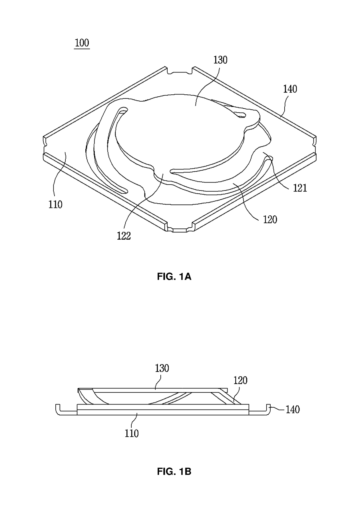
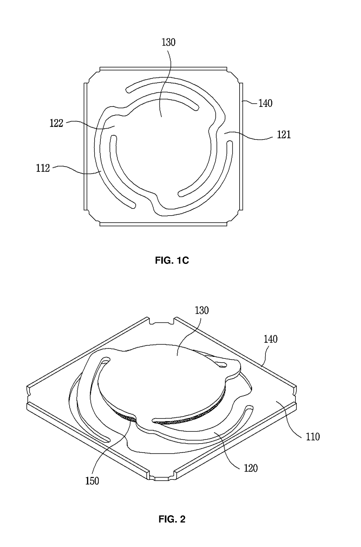
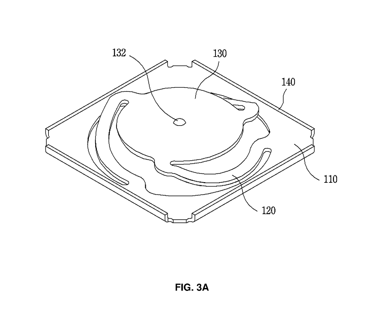
[0045]Hereinafter, exemplary embodiments of the present invention will be described in detail with refe...


PUM


Abstract

A resilient contact terminal having a structure that can be applied to various purposes. The contact terminal has: a base; a plurality of bridges of which one end is connected to the base, is spirally wound and extends in upward inclination, and which thus are vertically resilient; and a contact portion connected to the other end of each bridge. A gap portion separates the bridges and the contact portion, and the bridges and the base. The edge of the base is positioned further outward than the edge of the contact portion.

Description

REFERENCE TO RELATED APPLICATIONS[0001]This is a continuation of International Patent Application PCT / KR2018 / 000236 filed on Jan. 5, 2018, which designates the United States and claims priority of Korean Patent Application No. 10-2017-0002623 filed on Jan. 6, 2017, and Korean Patent Application No. 10-2017-0008540 filed on Jan. 18, 2017, and Korean Patent Application No. 10-2017-0048282 filed on Apr. 14, 2017, the entire contents of which are incorporated herein by reference.FIELD OF THE INVENTION[0002]The present invention relates to an elastic contact terminal, and more particularly, to an elastic contact terminal having a structure applied for a variety of purposes.BACKGROUND OF THE INVENTION[0003]Korean Patent Registration No. 1644119, filed by the present applicant, discloses an elastic electrical contact terminal including: a plate-shaped fixing part of which the lower surface can be reflow-soldered on a circuit substrate by using solder cream; a plate-shaped contact part spac...

Claims


Application Information

Patent Timeline
Patent Type & Authority Applications(United States)
IPC IPC(8): H05K7/20H01R13/24H01R12/55H05K1/02H05K9/00H01H1/24F28F3/00
CPCH05K7/2039H01R13/2407H01R12/55H05K1/0203H05K9/0026H01H1/24F28F3/00H01L23/367H05K2201/10371H01H2205/004H01H13/79H01H2203/002H01H2203/022H01H2203/024H01H2205/01H01H2215/008H01H2215/024H01L23/36H01R12/57H01R12/712H01R13/245H05K3/341H05K2201/0311H05K2201/10053H05K2201/1031Y02P70/50H01R12/707
Inventor KIM, SUN-KIKANG, TAE-MAN
Owner JOINSET
Why Eureka
Try Eureka