Hybrid transfer machine
a transfer machine and hybrid technology, applied in the direction of ink transfer from master sheets, printing presses, printing, etc., can solve the problems of excessive setting time, reduced space utilization efficiency, and increased operating cost, and achieve the effect of improving operability
- Summary
- Abstract
- Description
- Claims
- Application Information
AI Technical Summary
Benefits of technology
Problems solved by technology
Method used
Image
Examples
first embodiment
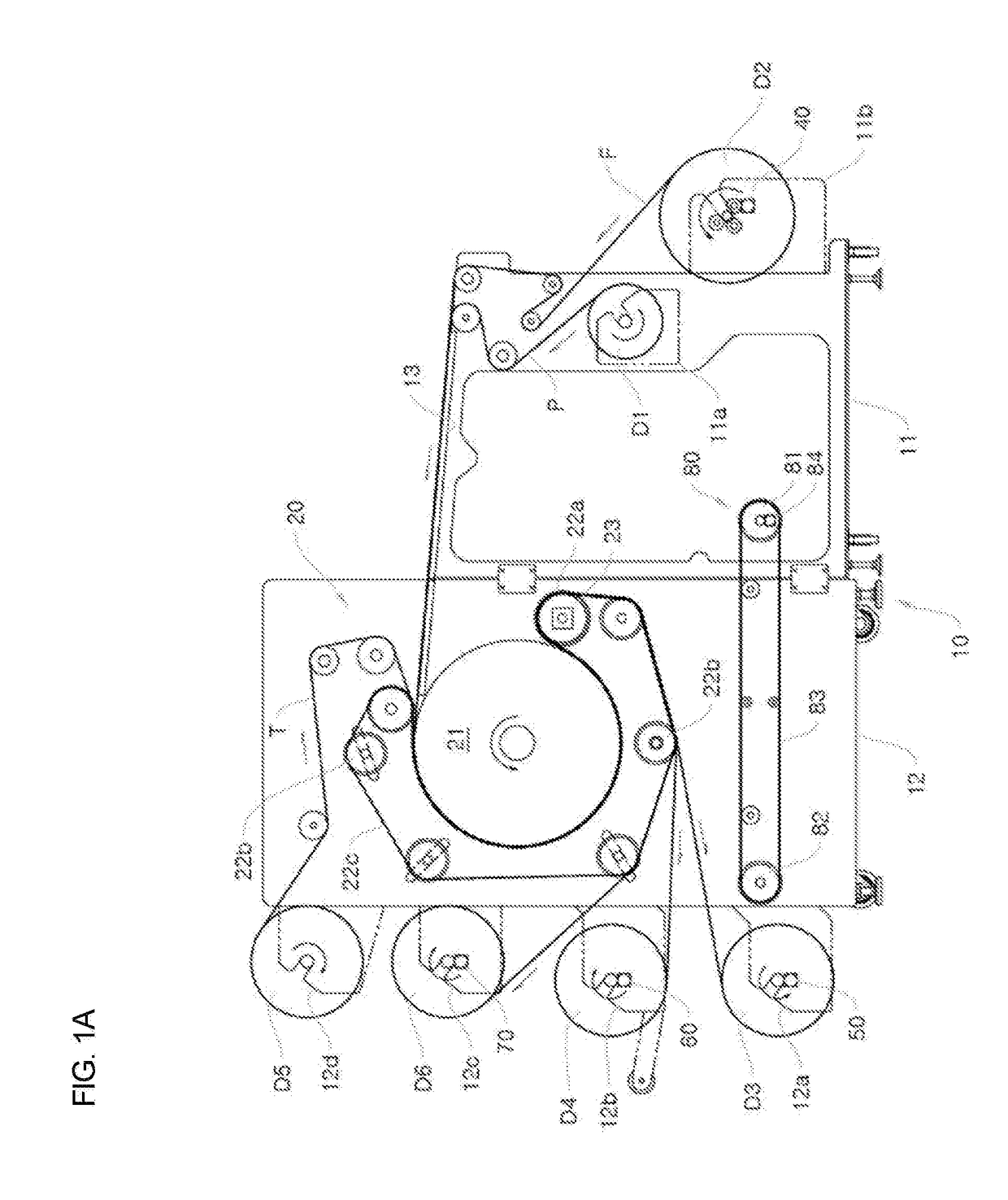
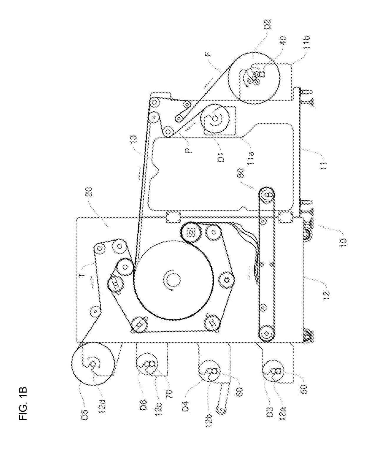
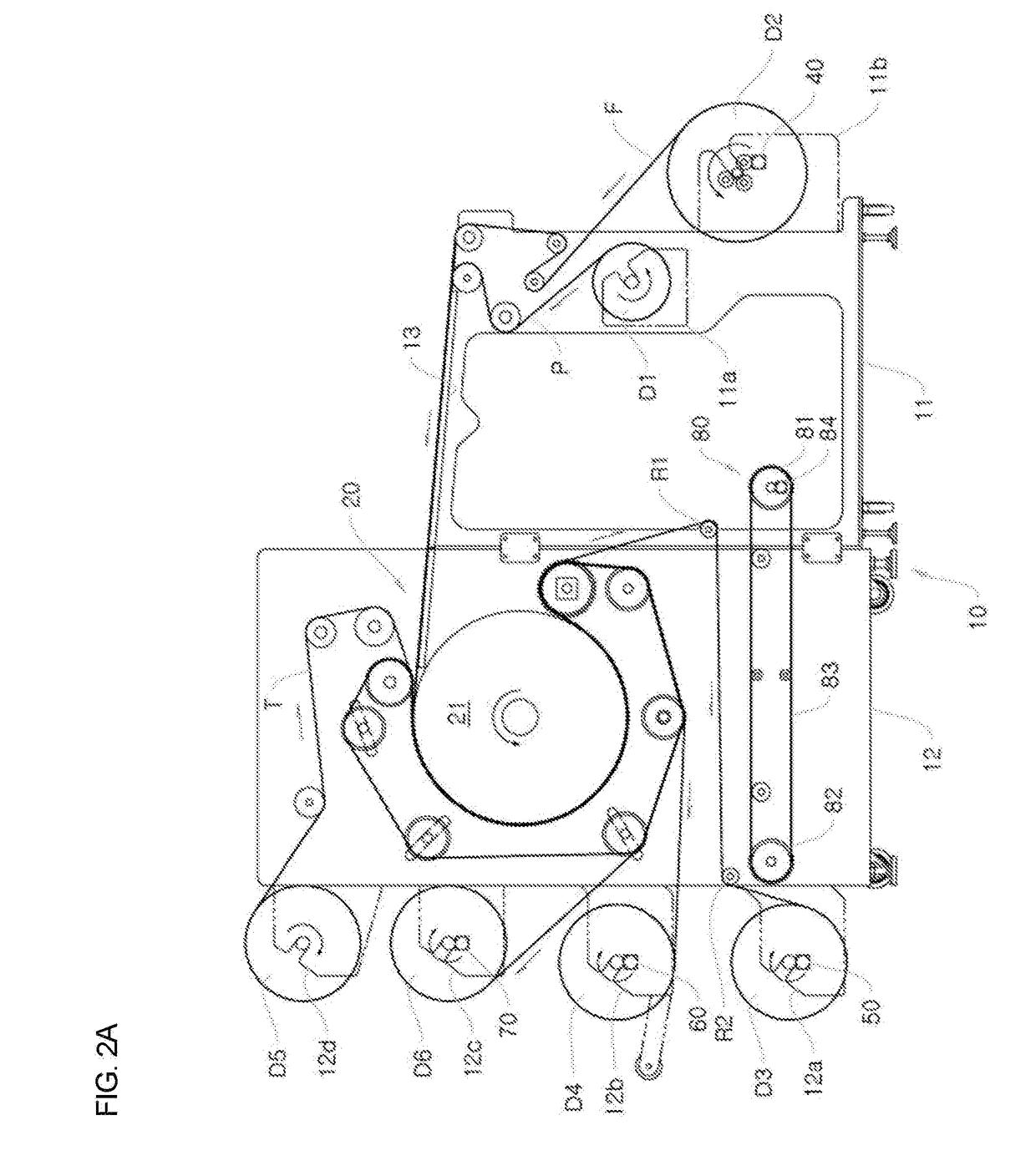
[0099]FIG. 4A is a front view showing a hybrid transfer machine according to a first piece-type embodiment of the present invention, and FIG. 4B is a view illustrating a preparation process of FIG. 4A.
[0100]The configuration of the first piece-type embodiment is the same as the first roll-type embodiment only except that a piece-type roller arm 30 is applied to the first embodiment of a piece type.
[0101]The piece-type roller arm 30 is installed in the fourth drum installation part 12b of a second body 12 in the form of a cantilever, and functions to guide transfer paper P, fed from a thermal transfer unit 20, to a transfer paper take-up drum D3 rotatably installed in a third drum installation part 12a.
[0102]As an example, transfer paper P, each piece of fabric F′, and tissue T (which may be omitted as desired) are discharged from the thermal transfer unit 20 in a superimposed state, and are separated from each other at a specific location (see FIGS. 4A and 4B). The transfer paper P...
second embodiment
[0116]FIG. 5A is a front view showing a hybrid transfer machine according to a second piece-type embodiment the present invention, and FIG. 5B is a view illustrating the preparation process of FIG. 5A.
[0117]The overall configuration of the second pieces-type embodiment is the same as that of the first piece-type embodiment only except that a third roller R3 is further included in the second piece-type embodiment.
[0118]The third roller R3 is rotatably installed in a first body 11 to be adjacent to a worktable 13, and functions to guide transfer paper P, exiting from a thermal transfer unit 20, to a first roller R1.
[0119]As an example, the transfer paper P, a piece of fabric F′, and tissue T (which may be omitted as desired) are discharged from the thermal transfer unit 20 in a superimposed state.
[0120]Meanwhile, when they are moved in the superimposed state for a long period of time, the transfer paper P and the piece of fabric F′ are shaken due to vibrations during movement accordin...
third embodiment
[0123]FIG. 6A is a front view showing a hybrid transfer machine according to a third piece-type embodiment of the present invention, and FIG. 6B is a view illustrating a preparation process of FIG. 6A.
[0124]The overall configuration of the third embodiment is the same as that of the second embodiment only except that a fourth roller R4 and a fifth roller R5 are further included in the third embodiment.
[0125]The fourth roller R4 is rotatably installed between a third roller R3 and a conveyer 80 in a first body 11, and functions to guide transfer paper P, guided by the third roller R3, to a transfer paper take-up drum D3.
[0126]The fifth roller R5 is rotatably installed between the third roller R3 and the fourth roller R4 inside the first body 11, and functions to guide tissue T, exiting from a thermal transfer unit 20, to a tissue take-up drum D6.
[0127]As an example, the transfer paper P, a piece of fabric F′, and tissue T are discharged from the thermal transfer unit 20 in a superimp...
PUM
 Abstract
Description
Claims
Application Information
 - R&D
- Intellectual Property
- Life Sciences
- Materials
- Tech Scout
- Unparalleled Data Quality
- Higher Quality Content
- 60% Fewer Hallucinations
Browse by: Latest US Patents, China's latest patents, Technical Efficacy Thesaurus, Application Domain, Technology Topic, Popular Technical Reports.
© 2025 PatSnap. All rights reserved.Legal|Privacy policy|Modern Slavery Act Transparency Statement|Sitemap|About US| Contact US: help@patsnap.com


