Vehicle risk avoidance device

Active Publication Date: 2019-02-14
DENSO CORP
View PDF6 Cites 7 Cited by
  • Summary
  • Abstract
  • Description
  • Claims
  • Application Information

AI Technical Summary

Benefits of technology

[0009]In this manner, when the road surface condition is detected with the use of the tire mount sensor, the road surface condition can be detected without braking. Therefore, since the road surface condition can be d

Problems solved by technology

This makes it difficult to detect the slipperiness of the road with a high frequency during traveling of the

Method used


Image

  • Vehicle risk avoidance device
  • Vehicle risk avoidance device
  • Vehicle risk avoidance device

Examples


Example

First Embodiment

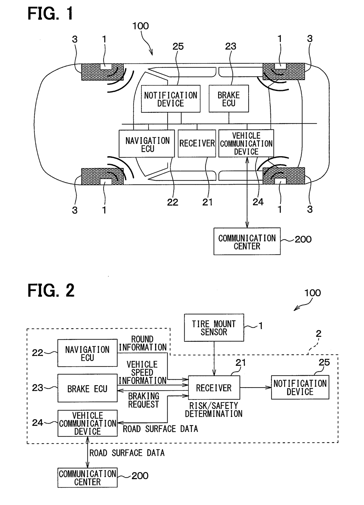
[0022]A vehicle risk avoidance device 100 according to the present embodiment will be described with reference to FIGS. 1 to 9. The vehicle risk avoidance device 100 according to the present embodiment estimates a road surface condition during traveling based on vibrations applied to a tread surface of a tire provided to each wheel of a vehicle and transmits an estimation result to a communication center, and performs a notification of a risk involved in the vehicle and a vehicle motion control based on the road surface condition.

[0023]As shown in FIGS. 1 and 2, the vehicle risk avoidance device 100 is configured to include tire mount sensors 1 provided on wheel sides and a vehicle body side system 2 including respective components provided on a vehicle body side. The vehicle body side system 2 includes a receiver 21, an electronic control device for navigation control (hereinafter referred to as a navigation ECU) 22, an electronic control device for brake control (h...

Example

Second Embodiment

[0071]In the present embodiment, the process to be executed by the receiver 21 is changed as compared with the first embodiment, and other processes are identical with those in the first embodiment. Therefore, only parts different from those in the first embodiment will be described.

[0072]As described above, in the first embodiment, the receiver 21 determines the risk involved in the vehicle based on the road surface data transmitted from the communication center 200. On the other hand, in the present embodiment, the receiver 21 determines whether there is the risk involved in the vehicle, or not, based on not the road surface data transmitted from the communication center 200, but the road surface data indicating the road surface condition detected by the tire mount sensor 1 of the host vehicle. Specifically, the road surface data transmitted from the tire mount sensor 1 is used when executing the process of determining the risk involved in the vehicle in Step S200...


PUM


Abstract

A tire mount sensor detects a road surface condition such as a type of a road surface and a road surface μ, and transmits road surface data indicating a detection result to a communication center. The communication center collects road surface data more precisely, and the vehicle receives the more precise road surface data from the communication center. Based on received more precise road surface data, the risk of the vehicle is determined. Thus, the road surface condition is detected using the tire mount sensor, so that the road surface condition is detected without braking. Accordingly, it is possible to detect the road surface condition with high frequency, so that the road surface condition is detected in wider area, and it is possible to perform the control more appropriately for avoiding the risk based on the road surface condition during a travel.

Description

CROSS REFERENCE TO RELATED APPLICATION[0001]This application is based on Japanese Patent Application No. 2016-30254 filed on Feb. 19, 2016, the disclosure of which is incorporated herein by reference.TECHNICAL FIELD[0002]The present disclosure relates to a vehicle risk avoidance device that detects a road surface condition while a vehicle is traveling, and performs a control for avoiding a risk during the traveling based on the road surface condition, for example, a control for notifying a driver of the risk or generating a braking force acting on the vehicle.BACKGROUND ART[0003]Up to now, a road surface information distribution system that measures slipperiness of a road on which the vehicle is traveling, transmits the measured slipperiness to a communication center through a vehicle communication device, and communicates the slipperiness from the communication center to another vehicle has been disclosed (refer to Patent Literature 1). Specifically, in the road surface information...

Claims


Application Information

Patent Timeline
IPC IPC(8): B60W30/09B60W40/068B60W30/095G08G1/16B60W50/14
CPCB60W30/09B60W40/068B60W30/0956G08G1/163G08G1/166B60W50/14B60W2050/143B60C23/20B60W10/184B60W30/02B60T8/1725B60T8/173B60T2210/12B60T2210/14B60T2240/03B60C23/064G08G1/0112G08G1/0129G08G1/0141G08G1/096716G08G1/096725G08G1/096741G08G1/096775G08G1/164B60W30/18172B60W2520/28B60W2422/70B60W2552/30B60W2756/10B60W2556/50B60T7/12B60T8/1763B60T8/172
Inventor MORI, MASASHIIKEMOTO, HIDEYUKISEKIZAWA, TAKATOSHI
Owner DENSO CORP
Why Eureka
Try Eureka