Rotor for a turbomachine

Active Publication Date: 2019-02-14
MTU AERO ENGINES GMBH
View PDF9 Cites 0 Cited by
  • Summary
  • Abstract
  • Description
  • Claims
  • Application Information

AI Technical Summary

Benefits of technology

[0040]A component damage may also be used as a characteristic, respectively indication of the service life of a component. Thus, the exemplarily indicated crack depths may at least affect the service life of the component. Thus, via the non-circular, in particular elliptical cross section of the through bore, the inventive rotor makes it possible to advantageously prolong the service life of the rotor.
[0041]Another factor that affects crack formation, as described above, is the component temperature. High temperatures, which may affect the crack formation, occur in low-pressure turbines and/or high-pressure turbines of aircraft engines, in particular. For that reason, in low-pressure turbines and/or high-pressure turbines of aircraft engines, in particular, the rotor according to the present invention may advantageously at least reduce a component damage and/or prolong the service

Problems solved by technology

Depending on the operating conditions, these connectio

Method used


Image

  • Rotor for a turbomachine
  • Rotor for a turbomachine

Examples


Embodiment Construction

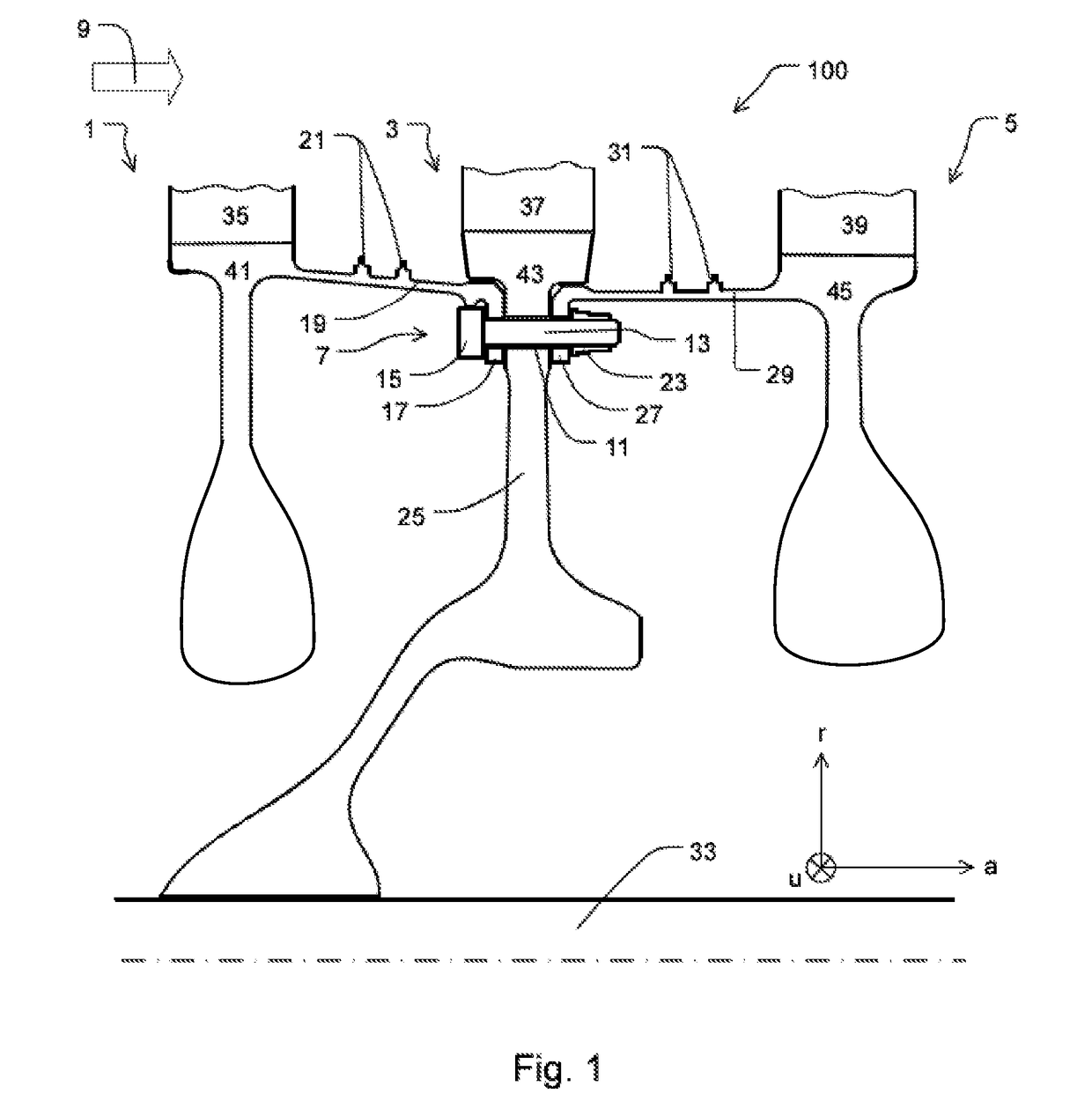
[0047]FIG. 1 shows an inventive rotor 100 for an axial turbomachine having three rotor stages 1, 3, 5 that are interconnected by a bolt 7.

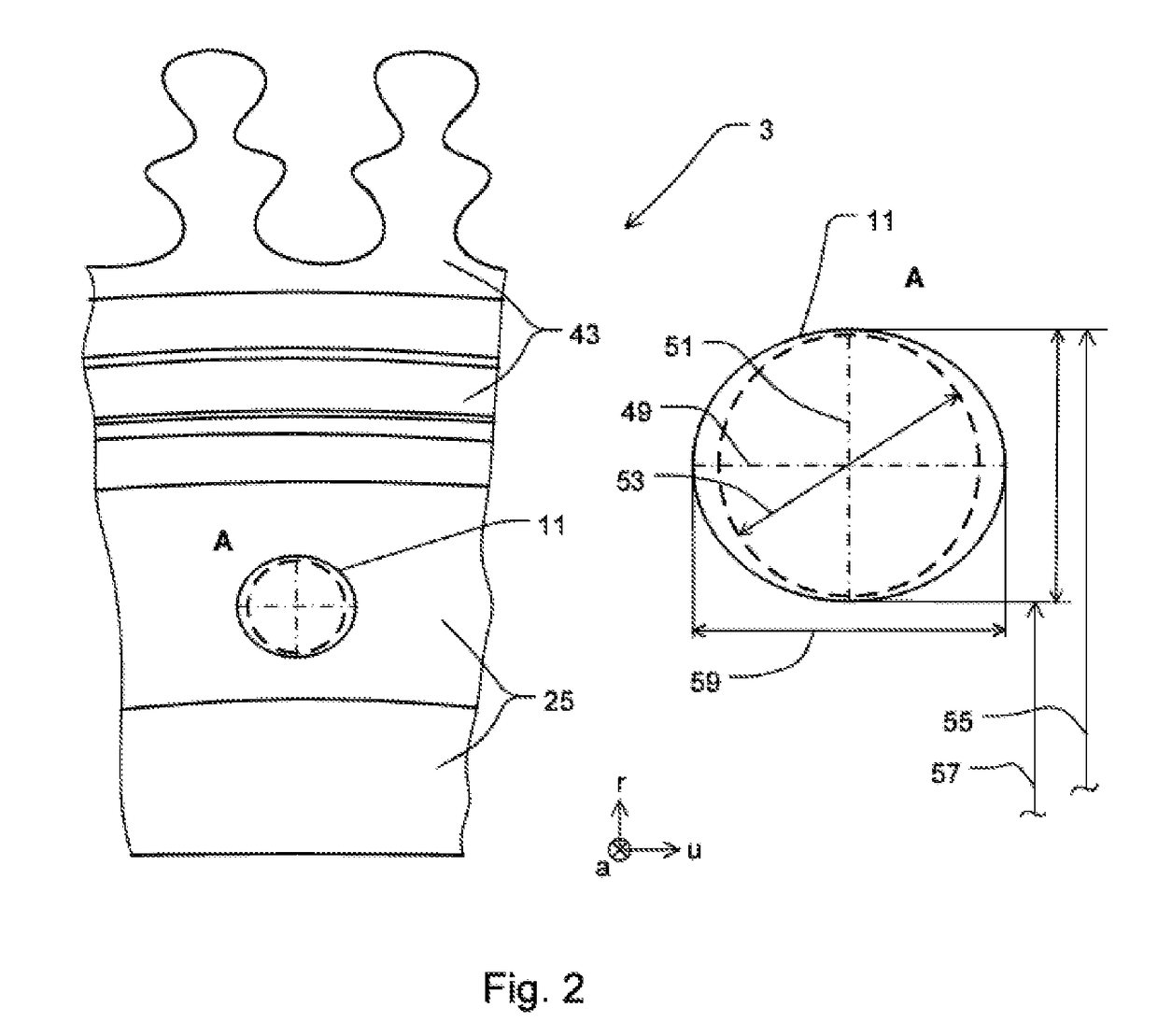
[0048]Rotor stage 3, which is in the middle in FIG. 1 and, viewed in through flow direction 9 of the turbomachine, is second rotor stage 3 of rotor 100, features a through bore 11 through rotor disk 25 of second rotor stage 3, through which bolt shank 13 of bolt 7 is passed or inserted. The cross-sectional shape of through bore 11 is shown in greater detail in FIG. 2. A flange 17 of first rotor stage 1 is configured on axial downstream end region of rotor arm 19. In addition, rotor arm 19 has sealing tips 21 for sealing a possible leakage flow between rotor arm 19 and a guide vane (not shown in FIG. 1).

[0049]Bolt 7 has a bolt head 15 that rests against flange 17 of first rotor stage 1. Purely exemplarily, at the periphery thereof, bolt head 15 rests against a shoulder of rotor arm 19. This resting against may act as a locking against rotation upon...


PUM


Abstract

A rotor (100) for a turbomachine is provided, having at least two bladed, detachably interconnected rotor stages (1, 3, 6), a flange (17) of a first rotor stage (1) being attached to a rotor disk (25) of a second, adjacent rotor stage (3) via at least one fastening element (7). The rotor disk (25) has a through bore (11) for connecting the two rotor stages (1, 3) by the fastening element (7); the through bore (11) having a cross section that is larger in the circumferential direction (u) of the rotor disk (25) than in the radial direction (r) thereof.

Description

[0001]This claims the benefit of German Patent Application DE 102017214058.5, filed Aug. 11, 2017 and hereby incorporated by reference herein.[0002]The present invention relates to a rotor for a turbomachine, having at least two bladed, detachably interconnected rotor stages.BACKGROUND[0003]The turbomachine rotors, as known from the related art, have a plurality of rotor stages, it being possible for the rotor stages to be interconnected in different ways. Flange joints are often used, a rotor stage connected by a shaft being connected to other rotor stages by flanges. Depending on the operating conditions, these connections of the rotor stages are often subject to high loads. Both the stress level, as well as the stress amplitudes can determine the service life of the particular components.SUMMARY OF THE INVENTION[0004]It is an object of the present invention to provide a further rotor that at least minimizes the mentioned problems.[0005]A rotor for a turbomachine is provided that ...

Claims


Application Information

Patent Timeline
IPC IPC(8): F01D5/06
CPCF01D5/066F05D2220/30F05D2230/60F05D2250/14Y02T50/60
Inventor SIEBEL, MATTHIAS
Owner MTU AERO ENGINES GMBH
Why Eureka
Try Eureka