An elongated lead frame and a method of manufacturing an elongated lead frame

a technology of elongated lead frame and curved lead frame, which is applied in the direction of printed circuit manufacturing, printed circuit aspects, lighting and heating apparatus, etc., can solve the problems of insufficient, limited flexibility of the above discussed flexible led strip and the led 3d curved lead frame of the cited us application, etc., to improve heat management of the light emitter islands, improve heat management, and accelerate the further metal element to the device

Active Publication Date: 2019-02-14
SIGNIFY HLDG BV
View PDF2 Cites 7 Cited by
  • Summary
  • Abstract
  • Description
  • Claims
  • Application Information

AI Technical Summary

Benefits of technology

[0038]The further metal element provides an additional heat sink to the light emitter island and thereby the heat management of the light emitter islands is improved and more heat can be provided, in use, to an ambient of the elongated lead frame that is provided with light emitters. Further advantage of the further metal element is that they may also be arranged to act as an optical element such that it fulfills the function of a reflector and of a heat sink. Alternatively, parts of the further metal elements that protrude away from the elongated lead frame may also be used to fasten the elongated lead frame to other devices, for example, by clamping the parts of the further metal elements in between other elements of the device, or using a screw to faster the further metal element to the device, etc. The fu

Problems solved by technology

This flexibility is rather limited and there is a need for more flexible strip-shaped LED lead frames.
The flexibility of the above discussed flexible LED strips and the LED 3d curved lead frame of the cited US applic

Method used


Image

  • An elongated lead frame and a method of manufacturing an elongated lead frame
  • An elongated lead frame and a method of manufacturing an elongated lead frame
  • An elongated lead frame and a method of manufacturing an elongated lead frame

Examples


Embodiment Construction

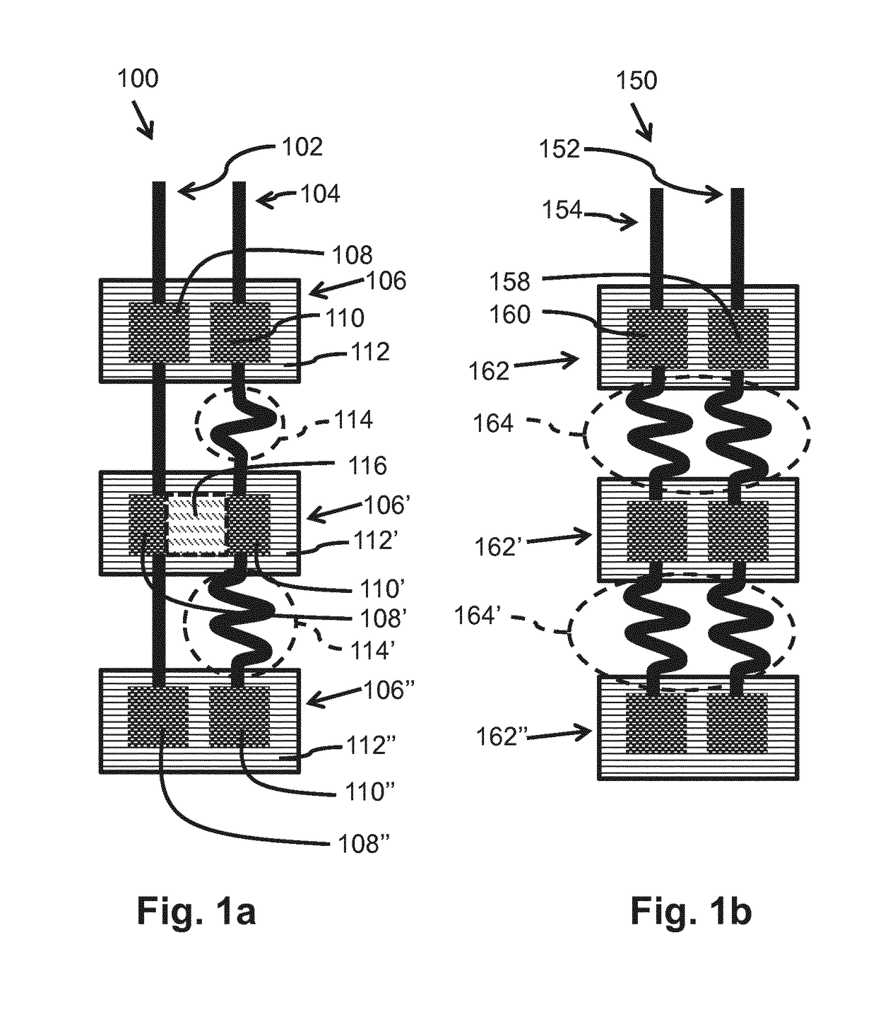
[0058]FIG. 1a schematically shows a top view of an elongated lead frame 100 for a plurality of solid state light emitters 116. The elongated lead frame 100 comprises a plurality of light emitter islands 106, 106′, 106″ that comprise two electrodes 108, 110, 108′, 110′, 108″, 110″. Each light emitter island 106, 106′, 106″ has a rigid structure. In the embodiment of FIG. 1a, the rigid structure is provided by stiffeners 112, 112′, 112″ that are formed by a plate of an electrically isolating material. The plate is made out of a relatively stiff material that is difficult to bend. On the stiffeners 112, 112′, 112″ are provided the two electrodes 108, 110, 108′, 110′, 108″, 110″. Each pair of electrodes 108, 110, 108′, 110′, 108″, 110″ is for receiving a solid state light emitter 116. For example, one solid state light emitter 116 is schematically drawn and indicated with number 116. The elongated lead frame comprises a first patterned layer with two electrically conductive tracks 102, ...


PUM


Abstract

An elongated lead frame (100) for a plurality of solid state light emitters (116), an elongated lighting assembly and a method of manufacturing an elongated lead frame are provided. The elongated lead frame comprises a first patterned layer (310) of an electrically conductive material and a second patterned layer (320) of an electrically isolating material. The first patterned layer comprising two electrically conductive tracks (102) that comprise first structures (316, 316′) for a first layer of a stack of light emitter islands and two electrically conductive connections between the first structures, at least one of the electrically conductive tracks comprises in between pairs of neighboring first structures a winded portion for forming a flexible electrically conductive connection in between the pairs of neighboring first structures. The second patterned layer comprising second structures for a second layer of the stack of the light emitter islands, the second patterned layer is provided on top of the first patterned layer.

Description

FIELD OF THE INVENTION[0001]The invention relates to an elongated lead frame for a plurality of solid state light emitters, such as, for example, Light Emitting Diodes (LEDs).[0002]The invention further relates to an elongated lighting assembly.[0003]The invention also relates to a method of manufacturing an elongated lead frame for a plurality of solid state light emitters.BACKGROUND OF THE INVENTION[0004]For car manufacturers it is important to have a signature design for the light sources of the car. Often the light sources comprise a strip shaped light source with Light Emitting Diodes (LEDs) that follows curves in several dimensions, for example, in a first dimension that is defined by a corner of the car and in a second dimension that follows a portion of a partly circular circumference of a front light. Often car manufacturers have to order strip shaped lighting assemblies that are already manufactured in the required shape. There is a need to have a general elongated shaped ...

Claims


Application Information

Patent Timeline
IPC IPC(8): H01L33/62H01L23/495H01L33/56H01L25/075H01L33/64H01L21/48
CPCH01L33/62H01L23/4951H01L23/49541H01L23/49568H01L33/56H01L23/49575H01L25/0753H01L33/647H01L21/4821H05K1/189H05K3/202H05K2201/066H05K2201/09263H05K2201/10106H05K2201/2009F21Y2103/10F21Y2107/70
Inventor KUMS, GERARDSWEEGERS, NORBERTUS ANTONIUS MARIACROMPOVETS, FLORIS MARIA HERMANSZKLEIJNEN, CHRISTIAN
Owner SIGNIFY HLDG BV
Why Eureka
Try Eureka