Engine heat retention structure

a technology of heat retention structure and engine, which is applied in the direction of machines/engines, transportation and packaging, jet propulsion mounting, etc., to achieve the effect of further reducing heat loss through spa

Active Publication Date: 2019-02-28
MAZDA MOTOR CORP
View PDF19 Cites 2 Cited by
  • Summary
  • Abstract
  • Description
  • Claims
  • Application Information

AI Technical Summary

Benefits of technology

[0014]According to this structure, since the arm part is disposed substantially at the same height as the space, the heat loss via the space is further reduced.

Problems solved by technology

However, as JP2013-119384A does not disclose how to reduce the weight and the cost of the covering member, there is room for improvement.

Method used


Image

  • Engine heat retention structure
  • Engine heat retention structure
  • Engine heat retention structure

Examples


embodiment

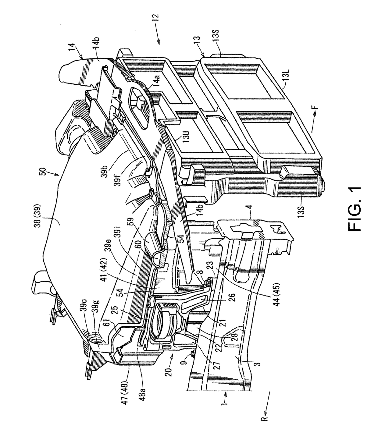
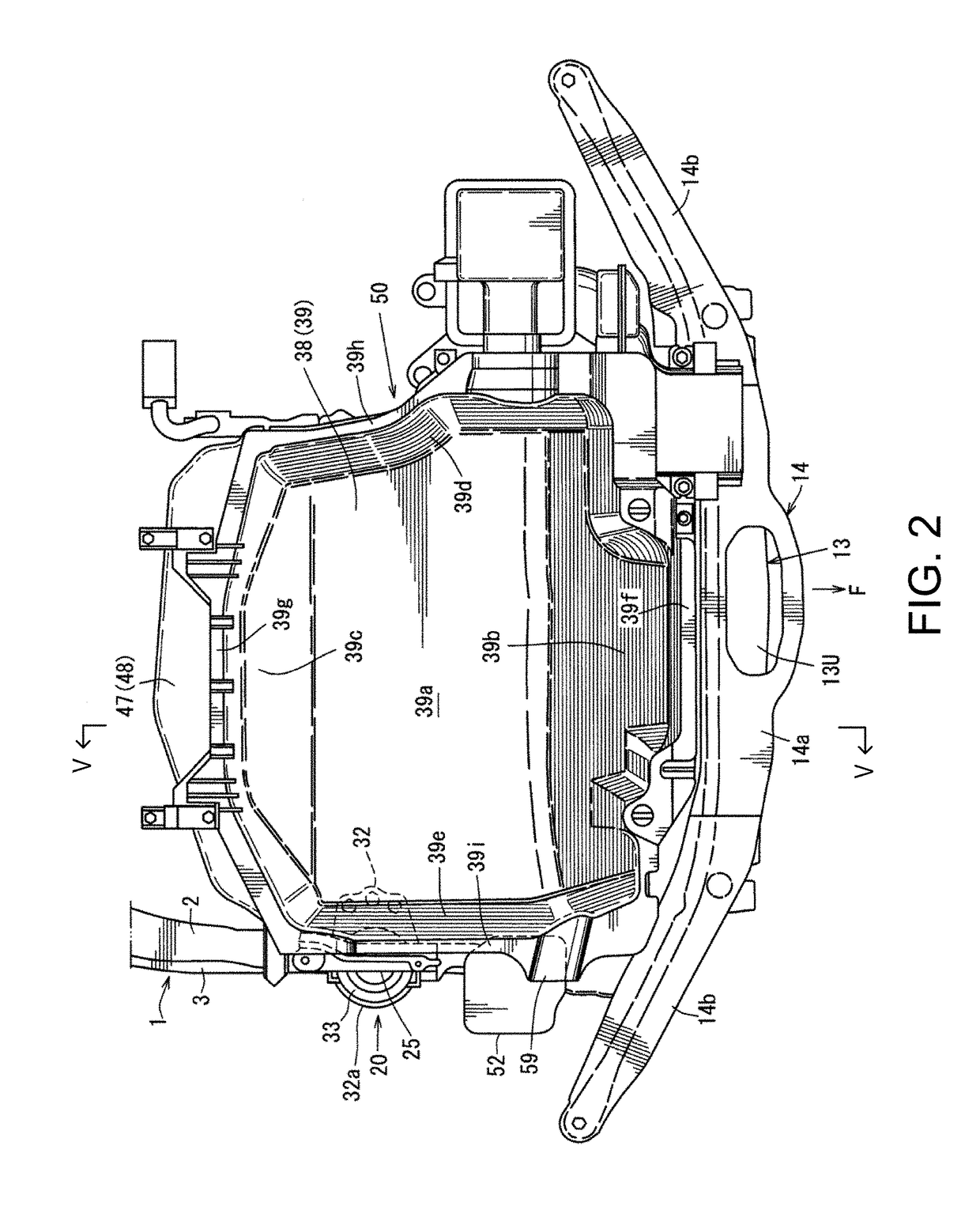
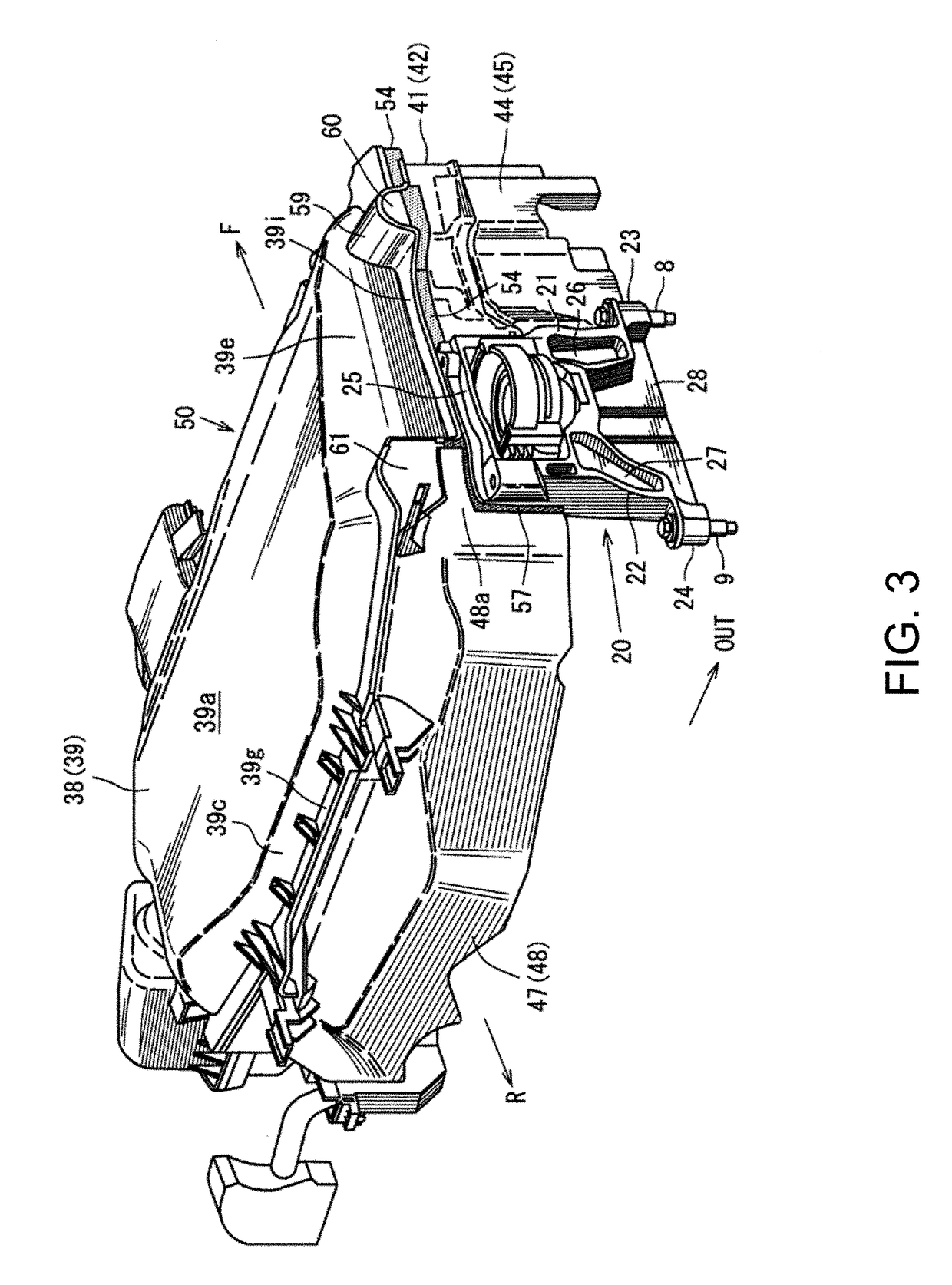
[0026]Below, one embodiment of the present disclosure is described in detail based on the accompanying drawings. The drawings illustrate a heat retention structure of an engine, where FIG. 1 is a perspective view of the heat retention structure seen from an upper right position, FIG. 2 is a plan view of FIG. 1, FIG. 3 is a perspective view of the heat retention structure seen from a rear upper position, FIG. 4 is a right side view illustrating the heat retention structure seen from an outward position in vehicle width directions, and FIG. 5 is a left side view illustrating the heat retention structure seen from an inward position in the vehicle width directions.

[0027]Note that throughout the drawings, an arrow F indicates forward of the vehicle, an arrow R indicates rearward of the vehicle, an arrow IN indicates inward in the vehicle width directions, an arrow OUT indicates outward in the vehicle width directions, and an arrow UP indicates upward of the vehicle.

[0028]Before describi...


PUM


Abstract

A vehicle is provided, which includes an engine bay having an upper wall, side walls, a front wall, and a rear wall, an engine disposed inside the engine bay, and a dedicated heat retention member provided inside the engine bay, the dedicated heat retention member comprising an upper lid part covering the engine from above to be openable and closable, and side-wall parts covering a side of the engine. A portion of the side-wall parts is comprised of an engine mount bracket configured to support mounts of the engine, instead of the dedicated heat retention member.

Description

TECHNICAL FIELD[0001]The present disclosure relates to a heat retention structure of an engine including a dedicated heat retention member comprised of an upper lid part covering the engine from above to be openable and closable, and side-wall parts covering a side of the engine.BACKGROUND OF THE DISCLOSURE[0002]Generally, if a vehicle is stopped outdoors for a given period of time (e.g., 8 hours or longer), the engine temperature drops to the ambient temperature. In order to prevent the engine temperature from falling to the ambient temperature, a heat retention member comprised of an upper lid part covering the engine from above and side-wall parts covering the sides of the engine may be provided. The heat retention member suppresses the drop of the engine temperature, makes a restart of the engine possible from the highest possible temperature, reduces the fuel injection amount during an engine warm-up, improves fuel consumption, makes a quick engine warm-up possible, and keeps e...

Claims


Application Information

Patent Timeline
Patent Type & Authority Applications(United States)
IPC IPC(8): B60H1/00B60K11/06B60K11/08
CPCB60H1/00028B60K11/06B60K11/08F02B77/11B60K5/12B60K5/1208
Inventor TANAKA, YUKIYAOKAMURA, KAZUMIFUJIAKI, TOMO
Owner MAZDA MOTOR CORP
Why Eureka
Try Eureka