Magnetic recording medium, magnetic recording medium manufacturing apparatus, and method of manufacturing a magnetic recording medium

a technology of magnetic recording medium and manufacturing apparatus, which is applied in the field of magnetic recording medium, magnetic recording medium manufacturing apparatus, and method of manufacturing a magnetic recording medium, can solve the problems of large loss of space between the recording/reproducing head and the surface of the second magnetic layer, deterioration of the magnetization characteristics of both magnetic layers, and large drop in the signal level of the output signal

Inactive Publication Date: 2008-03-13
TDK CORPARATION
View PDF0 Cites 15 Cited by
  • Summary
  • Abstract
  • Description
  • Claims
  • Application Information

AI Technical Summary

Benefits of technology

[0010]The present invention was conceived in view of the problems described above and it is an object of the present invention to provide a magnetic recording medium that has a higher recording density, that is capable of bidirectional recording and reproducing and for which spacing loss can be avoided during recording and reproducing, and also to provide a magnetic recording medium manufacturing apparatus and a method of manufacturing a magnetic recording medium capable of manufacturing such magnetic recording medium.
[0012]According to this magnetic recording medium, by including the first metal thin-film magnetic layer and the second metal thin-film magnetic layer that respectively include the former growth portions that are formed of parts where the columns have grown in the thickness direction of the non-magnetic substrate (i.e., base end parts of the columns) and the latter growth portions that are formed of parts where the columns have grown so as to become inclined to a longitudinal direction of the non-magnetic substrate and arc-shaped in profile (i.e., the front-end parts of the columns), forming the former growth portions in the first metal thin-film magnetic layer makes it possible to form the first metal thin-film magnetic layer with the desired smoothness, and in turn the first metal thin-film magnetic layer having the desired smoothness makes it possible to avoid deterioration in the smoothness of the second metal thin-film magnetic layer formed on the first metal thin-film magnetic layer. Also, even if extremely small concaves and convexes that could not be absorbed by forming the former growth portions in the first metal thin-film magnetic layer are present in the surface of the first metal thin-film magnetic layer, forming the former growth portions in the second metal thin-film magnetic layer will still make it possible to form the second metal thin-film magnetic layer with the desired smoothness. Accordingly, unlike a magnetic recording medium manufactured according to the conventional method of manufacturing, it is possible to produce extremely small concaves and convexes that can reduce the friction (i.e., concaves and convexes of substantially the same size as the concaves and convexes formed in advance in the surface of the non-magnetic substrate) while sufficiently improving the overall smoothness of the magnetic recording medium to a level where the occurrence of spacing loss is avoided. As a result, it is possible to sufficiently improve both the signal level of the output signal when the tape is running forwards and the signal level of the output signal when the tape is running in reverse while avoiding deterioration in the tape running characteristics during recording and reproducing.
[0014]With this construction, it is possible to make the signal level of the output signal from a magnetic head substantially equal when the tape is running both forwards and in reverse during bidirectional recording and reproducing. Since it is possible to reproduce recorded data without a large change in the recording / reproducing conditions between when the tape is running forwards and when the tape is running in reverse, it is possible to sufficiently reduce the manufacturing cost of a recording / reproducing apparatus by an amount corresponding to the simplification of recording / reproducing control.
[0016]With this construction, it is possible to provide a magnetic recording medium with a sufficiently high coercivity. By doing so, it is also possible to maintain a sufficient magnetization state for recorded data to be read properly even when the width of the data recording tracks is reduced and / or the length of one bit on each data recording track is reduced to increase the recording density (a state where the influence of adjacent bits in the track width direction and / or the track length direction becomes prominent).
[0019]According to this magnetic recording medium manufacturing apparatus and method of manufacturing a magnetic recording medium, by consecutively forming the first metal thin-film magnetic layer and the second metal thin-film magnetic layer by forming the former growth portions formed of base end parts of the columns by supplying oxygen gas to the deposition start point of the deposition region to grow the columns in the thickness direction of the non-magnetic substrate and forming the latter growth portions formed of the remaining parts (i.e., front end parts) of the columns by growing the columns from the deposition start point to the deposition end point so as to become inclined to the longitudinal direction of the non-magnetic substrate and arc-shaped in profile, it is possible to reliably and easily manufacture a magnetic recording medium where the ratios of the thicknesses of the former growth portions to the thicknesses of the latter growth portions is in the desired range, or in other words, a magnetic recording medium with the desired smoothness.

Problems solved by technology

This means that with the conventional magnetic recording medium, due to the production of large concaves and convexes in the surface of the second magnetic layer, during the recording and reproducing of data, a large spacing loss is produced between a recording / reproducing head and the surface of the second magnetic layer.
Accordingly, with the conventional magnetic recording medium, there are the problems of deterioration in the magnetization characteristics of both magnetic layers and of a large fall in the signal level of an output signal during the reading of a magnetic signal.

Method used


Image

  • Magnetic recording medium, magnetic recording medium manufacturing apparatus, and method of manufacturing a magnetic recording medium
  • Magnetic recording medium, magnetic recording medium manufacturing apparatus, and method of manufacturing a magnetic recording medium
  • Magnetic recording medium, magnetic recording medium manufacturing apparatus, and method of manufacturing a magnetic recording medium

Examples


example 1

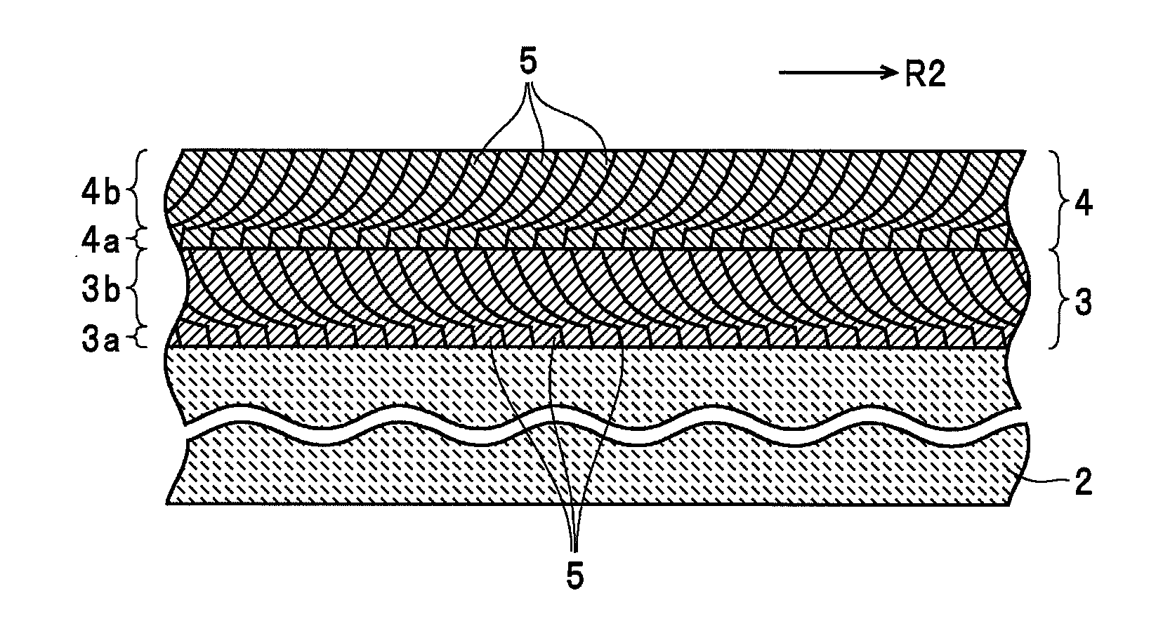
[0078]The first magnetic layer and the second magnetic layer were formed in the mentioned order on the non-magnetic substrate 2 so that the thickness of the former growth portions of the first magnetic layer was 4 nm, the thickness of the latter growth portions of the first magnetic layer was 29 nm, the thickness of the former growth portions of the second magnetic layer was 6 nm, and the thickness of the latter growth portions of the second magnetic layer was 51 nm. As a result, the thickness of the first magnetic layer was 33 nm and the thickness of the second magnetic layer was 57 nm, so that the ratio of the thickness of the first magnetic layer to the thickness of the second magnetic layer was 0.58. Also, the ratio of the thickness of the former growth portions to the thickness of the latter growth portions of the first magnetic layer was 0.14 and the ratio of the thickness of the former growth portions to the thickness of the latter growth portions of the second magnetic layer...

example 2

[0079]The first magnetic layer and the second magnetic layer were formed in the mentioned order on the non-magnetic substrate 2 so that the thickness of the former growth portions of the first magnetic layer was 4 nm, the thickness of the latter growth portions of the first magnetic layer was 28 nm, the thickness of the former growth portions of the second magnetic layer was 5 nm, and the thickness of the latter growth portions of the second magnetic layer was 47 nm. As a result, the thickness of the first magnetic layer was 32 nm and the thickness of the second magnetic layer was 52 nm, so that the ratio of the thickness of the first magnetic layer to the thickness of the second magnetic layer was 0.62. Also, the ratio of the thickness of the former growth portions to the thickness of the latter growth portions of the first magnetic layer was 0.14 and the ratio of the thickness of the former growth portions to the thickness of the latter growth portions of the second magnetic layer...

example 3

[0080]The first magnetic layer and the second magnetic layer were formed in the mentioned order on the non-magnetic substrate 2 so that the thickness of the former growth portions of the first magnetic layer was 4 nm, the thickness of the latter growth portions of the first magnetic layer was 31 nm, the thickness of the former growth portions of the second magnetic layer was 5 nm, and the thickness of the latter growth portions of the second magnetic layer was 42 nm. As a result, the thickness of the first magnetic layer was 35 nm and the thickness of the second magnetic layer was 47 nm, so that the ratio of the thickness of the first magnetic layer to the thickness of the second magnetic layer was 0.74. Also, the ratio of the thickness of the former growth portions to the thickness of the latter growth portions of the first magnetic layer was 0.13 and the ratio of the thickness of the former growth portions to the thickness of the latter growth portions of the second magnetic layer...


PUM

PropertyMeasurementUnit
thicknessaaaaaaaaaa
inclination angleaaaaaaaaaa

Abstract

A magnetic recording medium includes a first metal thin-film magnetic layer and a second metal thin-film magnetic layer, which respectively include a plurality of columns and have magnetization easy axes that are inclined in opposite directions, formed in that order on a non-magnetic substrate. Both metal thin-film magnetic layers include former growth portions that comprise base end parts of the respective columns and latter growth portions that comprise remaining parts of the respective columns on front-end sides of the columns. The former growth portions are formed by the columns growing in a thickness direction of the non-magnetic substrate. The latter growth portions are formed by the columns growing so as to become inclined to a length of the non-magnetic substrate and arc-shaped in profile.

Description

BACKGROUND OF THE INVENTION[0001]1. Field of the Invention[0002]The present invention relates to a magnetic recording medium on which a first metal thin-film magnetic layer and a second metal thin-film magnetic layer, whose magnetization easy axes are inclined in opposite directions, are formed in the mentioned order on a non-magnetic substrate and to a method of manufacturing a magnetic recording medium and a magnetic recording medium manufacturing apparatus for manufacturing such magnetic recording medium.[0003]2. Description of the Related Art[0004]Due to the increasing size of recorded data, it is necessary to increase the recording density of current information media. Many magnetic tapes marketed as backup media are so-called “wet-coating type magnetic recording media” where the saturation magnetization falls corresponding to the amount of binder (i.e., resin material) included in the magnetic layer to bind the magnetic powder. The included amount of binder also makes it diffi...

Claims


Application Information

Patent Timeline
Patent Type & Authority Applications(United States)
IPC IPC(8): G11B5/66C23C14/14
CPCC23C14/0021C23C14/042C23C14/085G11B5/84C23C14/562G11B5/64C23C14/30
Inventor NAKAYAMA, MASAOKANAZAWA, HIROMICHIWATASE, SHIGEHARUHAYASHI, TAKAHIRO
Owner TDK CORPARATION
Why Eureka
Try Eureka