
Eureka
For R&D, Eureka makes reading and utilizing patents & technical documents easy.
Eureka AIR
Designed for self-driven R&D workflows. Generate viable solutions, solve complex R&D challenges, empower your innovation with AI.

Eureka Materials
Designed for material experts only. Revolutionize your material R&D, from search, analyze, to developing new materials.

TechResearch
Generate reliable direction feasibility study reports for your R&D in just a few steps.

TechSeek
Discover and master advanced knowledge NOW. Basics, ideas, possibilities, all at once.

TechMind
As an expert in R&D Theories, TechMind can generates customized viable solutions instantly.

TechRisk
Analyze your overall solution with one click, know your potential R&D risks in advance.

TechMonitor
Get weekly tech updates, stay abreast of the latest tech innovations and key insights.
Measuring device for coefficient of thermal expansion and measurement method for coefficient of thermal expansion
- Summary
- Abstract
- Description
- Claims
- Application Information
AI Technical Summary
Benefits of technology
Problems solved by technology
Method used
Image

Examples
first exemplary embodiment
[0067]Description is made below on a CTE measuring device according to a first exemplary embodiment of the invention.
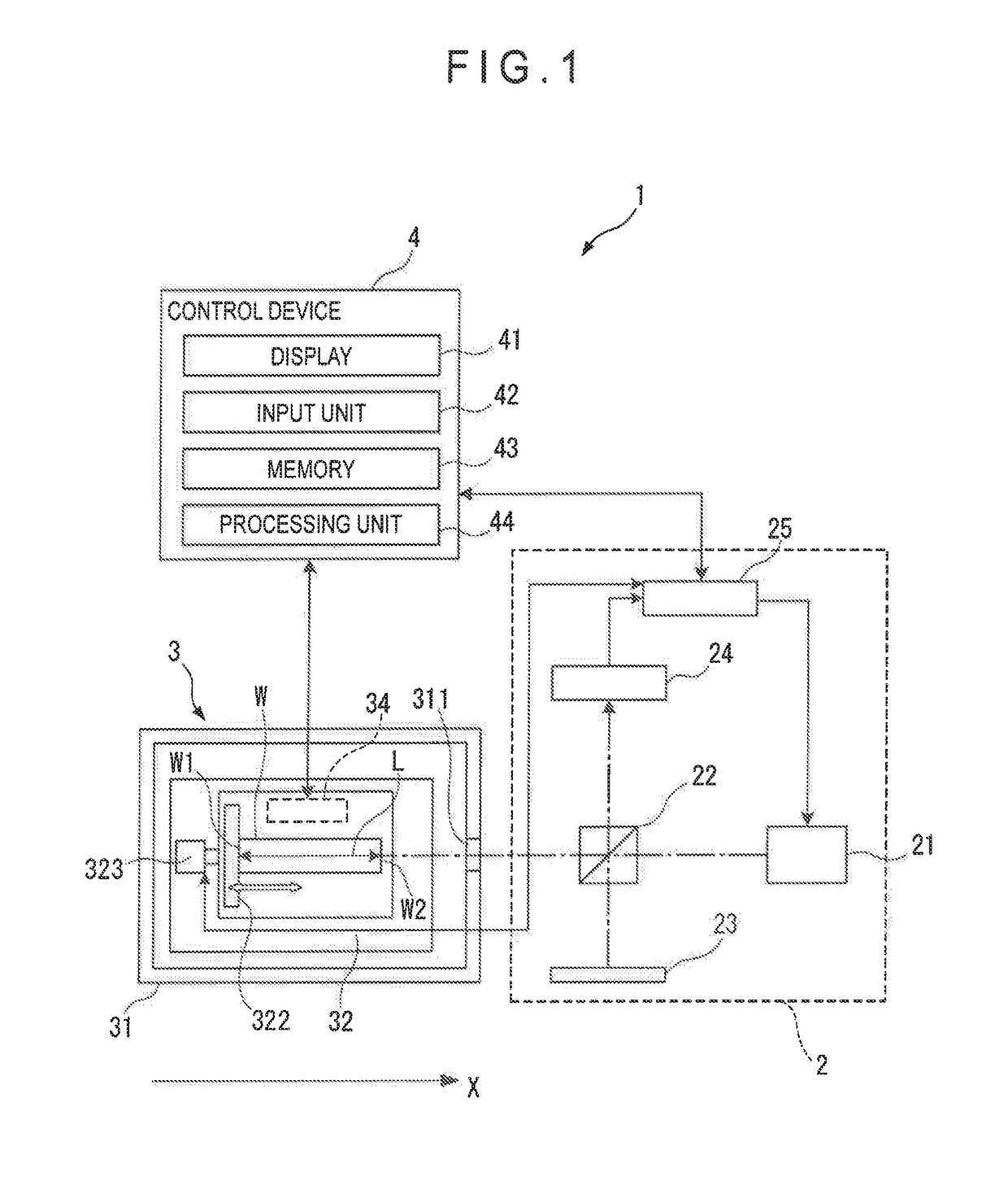
[0068]FIG. 1 schematically shows an arrangement of a CTE measuring device 1 according to the first exemplary embodiment.
[0069]As shown in FIG. 1, the CTE measuring device 1 includes an optical interferometer 2, a temperature control device 3, and a control device 4.
[0070]Arrangement of Temperature Control Device 3
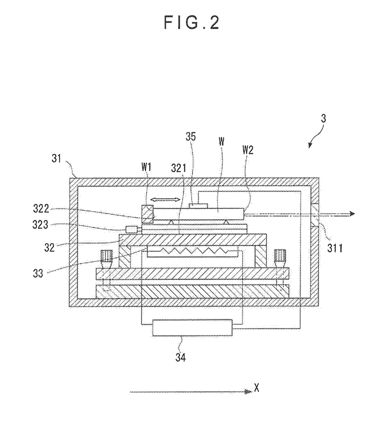
[0071]FIG. 2 schematically shows an example of the temperature control device 3.
[0072]The temperature control device 3, which corresponds to a temperature detector according to the invention, includes a variable temperature chamber 31 for accommodating an object W as shown in FIG. 2. The variable temperature chamber 31 includes walls made of a heat insulating material or an heat insulating layer. A table 32, which is made of a soaking plate, is installed in the variable temperature chamber 31, The table 32 has, for instance, a planar upper surface (mounting s...
second exemplary embodiment
[0153]Next, a second exemplary embodiment of the invention is described.
[0154]In the first exemplary embodiment, some data sets among the plurality of data sets are the same in evaluation index value s or CTE. FIG. 10 shows an example of the data sets that are the same in evaluation index value s and CTE.
[0155]Specifically, as shown in FIG. 10, a data set B and a data set C are translated in parallel to a data set A, the data set B containing pieces of verification data with the respective orders of interference that are reduced from those of the data set A by the same number (e.g., 1), the data set C containing the pieces of verification data with the respective orders of interference that are increased from those of the data set A by the same number (e.g., 1). The respective linear approximation functions of these data sets B, C are the same in gradient (ΔL / ΔT) as that of the data set A, while being different only in intercept. Thus, the CTE α and the evaluation index value s calc...
third exemplary embodiment
[0164]Next, a third exemplary embodiment of the invention is described.
[0165]In the first exemplary embodiment and the second exemplary embodiment, temperature intervals ΔTi (temperature variations) between temperatures for obtaining the actual data Li are exemplarily regular intervals. However, in such as a case, some data sets may be substantially the same in evaluation index value s while being different in CTE α.
[0166]FIG. 12 shows an example of data sets that are different in CTE but substantially the same in evaluation index value s.
[0167]Specifically, as represented by the formula (3), each of the pieces of verification data Di is a value obtained by adding / subtracting an integral multiple of the half wavelength to / from the actual data Li. Thus, if the data sets A, B, C include specific data sets in which one piece of verification data is the same and other pieces of verification data Di have the incremented or decremented orders of interference N, some of the data sets may b...
PUM
 Abstract
Description
Claims
Application Information
 - R&D Engineer
- R&D Manager
- IP Professional
- Industry Leading Data Capabilities
- Powerful AI technology
- Patent DNA Extraction
Browse by: Latest US Patents, China's latest patents, Technical Efficacy Thesaurus, Application Domain, Technology Topic, Popular Technical Reports.
© 2024 PatSnap. All rights reserved.Legal|Privacy policy|Modern Slavery Act Transparency Statement|Sitemap|About US| Contact US: help@patsnap.com