
Elastic wave device and method for producing the same

a technology of elastic wave and wave body, which is applied in the direction of impedence networks, electrical devices, etc., can solve the problems of insufficient reliability and occasional frequency fluctuation, and achieve the effect of excellent moisture resistan

Active Publication Date: 2019-02-28
MURATA MFG CO LTD
View PDF1 Cites 7 Cited by
  • Summary
  • Abstract
  • Description
  • Claims
  • Application Information

AI Technical Summary

Benefits of technology

The present invention provides elastic wave devices with improved moisture resistance. In this regard, the invention includes an intermediate layer that includes multiple layers with different acoustic impedance layers, including at least one low acoustic impedance layer and at least one high acoustic impedance layer. This arrangement effectively confines the energy of the elastic wave, resulting in reduced energy loss and improved efficiency. Furthermore, the intermediate layer may include a low acoustic velocity layer and a high acoustic velocity layer, which further enhances the confinement of the elastic wave energy. Additionally, the cover member may be made of an inorganic material or silicon, which improves moisture resistance of the elastic wave device.

Problems solved by technology

Thus, the elastic wave device of International Publication No. 2010 / 082571 has occasionally experienced frequency fluctuation, and the reliability thereof has not been sufficient.

Method used


Image

  • Elastic wave device and method for producing the same
  • Elastic wave device and method for producing the same
  • Elastic wave device and method for producing the same

Examples


first preferred embodiment

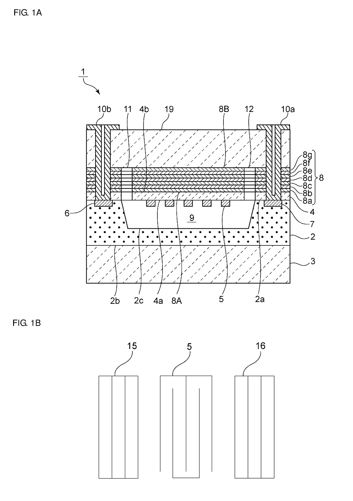
[0030]FIG. 1A is a schematic elevational cross-sectional view of an elastic wave device according to a first preferred embodiment of the present invention. FIG. 1B is a schematic plan view of an electrode structure of the elastic wave device according to the first preferred embodiment of the present invention.

[0031]An elastic wave device 1 uses a plate wave as a propagating elastic wave. The plate wave referred to herein is a wave, most of the elastic wave energy of which is concentrated in a piezoelectric body having a thickness less than or equal to the wavelength of the elastic wave. Thus, the structure is not limited to a so-called hollow structure in which the piezoelectric body is a thin plate or a thin film. Various thin films may be provided under the thin piezoelectric body so that most of the elastic wave energy is concentrated in the piezoelectric body, or a supporting substrate that supports these piezoelectric body and thin films may be provided.

[0032]The elastic wave d...

second preferred embodiment

[0086]FIG. 5 is a schematic elevational cross-sectional view of an elastic wave device according to a second preferred embodiment of the present invention. In an elastic wave device 21, a low acoustic velocity layer 20A and a high acoustic velocity layer 20B are formed as the intermediate layer instead of the acoustic reflecting layer. The acoustic velocity of the bulk waves propagating in the low acoustic velocity layer 20A is lower than the acoustic velocity of the elastic wave propagating in the piezoelectric thin film 4. The high acoustic velocity layer 20B is formed on the low acoustic velocity layer 20A. The acoustic velocity of the bulk waves propagating in the high acoustic velocity layer 20B is higher than the acoustic velocity of the elastic wave propagating in the piezoelectric thin film 4.

[0087]In this preferred embodiment, silicon oxide is used in the low acoustic velocity layer 20A. Alternatively, the low acoustic velocity layer 20A can be made of any appropriate mater...

third preferred embodiment

[0092]FIG. 6 is a schematic elevational cross-sectional view of an elastic wave device according to a third preferred embodiment of the present invention. In an elastic wave device 31, a low acoustic velocity layer 20A is formed as the intermediate layer instead of the acoustic reflecting layer. The acoustic velocity of the bulk waves propagating in the low acoustic velocity layer 20A is lower than the acoustic velocity of the elastic wave propagating in the piezoelectric thin film 4. The cover member 19 is a high acoustic velocity member, in which the acoustic velocity of the bulk waves propagating therein is higher than the acoustic velocity of the elastic wave propagating in the piezoelectric thin film 4. In this preferred embodiment, silicon oxide is used in the low acoustic velocity layer 20A. Alternatively, the low acoustic velocity layer 20A can use any appropriate material having a bulk wave acoustic velocity lower than the acoustic velocity of the elastic wave propagating i...


PUM


Abstract

An elastic wave device includes a supporting substrate including an upper surface including a recessed portion, a piezoelectric thin film on the supporting substrate to cover the recessed portion of the supporting substrate, an IDT electrode on a main surface of the piezoelectric thin film, the main surface being adjacent to the supporting substrate, and an intermediate layer on a main surface of the piezoelectric thin film, the main surface being remote from the supporting substrate. A space is defined by the supporting substrate and the piezoelectric thin film. The IDT electrode faces the space. Through holes are provided in the piezoelectric thin film and the intermediate layer to extend from a main surface of the intermediate layer to the space, the main surface being remote from the piezoelectric thin film. The elastic wave device further includes a cover member on the intermediate layer and covering opening ends of the through holes.

Description

CROSS REFERENCE TO RELATED APPLICATIONS[0001]This application claims the benefit of priority to Japanese Patent Application No. 2016-113678 filed on Jun. 7, 2016 and is a Continuation Application of PCT Application No. PCT / JP2017 / 014759 filed on Apr. 11, 2017. The entire contents of each application are hereby incorporated herein by reference.BACKGROUND OF THE INVENTION1. Field of the Invention[0002]The present invention relates to an elastic wave device in which an interdigital transducer (IDT) electrode is provided on a piezoelectric thin film, and to a method for producing the elastic wave device.2. Description of the Related Art[0003]Heretofore, elastic wave devices that use various elastic waves, such as surface acoustic waves, bulk waves, and plate waves, have been proposed. For example, International Publication No. 2010 / 082571 discloses an elastic wave device that uses a plate wave.[0004]International Publication No. 2010 / 082571 describes an elastic wave device in which a pi...

Claims


Application Information

Patent Timeline
Patent Type & Authority Applications(United States)
IPC IPC(8): H03H3/08H03H9/25H03H9/05H03H9/02H03H9/145
CPCH03H3/08H03H9/25H03H9/058H03H9/02992H03H9/14502H03H9/02228H03H9/02834H03H9/1064H03H3/02H03H2003/025H03H9/105
Inventor KIMURA, TETSUYAKISHIMOTO, YUTAKAOMURA, MASASHI
Owner MURATA MFG CO LTD
Learn More