Recording apparatus and recording method

a recording apparatus and recording method technology, applied in electrical equipment, printing, pictoral communication, etc., can solve the problems of image quality decline etc., to reduce granular impression, image quality decline, and image quality decline

Active Publication Date: 2019-03-07
CANON KK
View PDF0 Cites 0 Cited by
  • Summary
  • Abstract
  • Description
  • Claims
  • Application Information

AI Technical Summary

Benefits of technology

[0007]The present invention has been made in view of the above-described issues and aims at suppressing both the decrease in the image quality caused by the decrease in the granular impression and the uniformity between the overlap recording area and the non-overlap recording area and the decrease in the image quality caused by the decrease in the image density in the multiple scanning operations.

Problems solved by technology

In a case where the recording is performed by only one of the recording unit on the left side and the recording unit on the right side with respect to the entire area in the scanning direction on the recording medium, there is a fear that an image quality of an image obtained at a boundary between the area recorded by the recording unit on the left side and the area recorded by the recording unit on the right side may be decreased due to this density difference.
Herein, in a case where the recording is performed by using the above-described recording unit, when an arrangement of dots formed in an area where the left and right recording units perform the overlap recording (hereinafter, which will be referred to as an overlap recording area) and an arrangement of dots formed in an area where only one of the left and right recording units performs the recording (hereinafter, which will be referred to as a non-overlap recording area) are different from each other, there is a fear that the image quality may be decreased.
When the dot arrangement differs between the adjacent overlap recording area and non-overlap recording area, granular impression and uniformity differ between those areas, which causes the decrease in the image quality.
However, in a case where a skew conveyance of the recording medium between the scanning operations or a deviation in ink ejecting positions is caused between the scanning operations due to a fluctuation in a speed of the recording head, an inclination, or the like, there is a fear that the image density is largely decreased when the dots are formed at the exclusive and also complementary positions.
In particular, since the deviation in ink ejecting positions between the left and right recording units which is derived from a manufacturing error, an attachment error of the recording units, or the like may in addition to the above-described skew or fluctuation in the overlap recording area also be caused, the decrease in the image density becomes more conspicuous.

Method used


Image

  • Recording apparatus and recording method
  • Recording apparatus and recording method
  • Recording apparatus and recording method

Examples


first exemplary embodiment

[0035]Hereinafter, a first exemplary embodiment of the present invention will be described in detail with reference to the drawings.

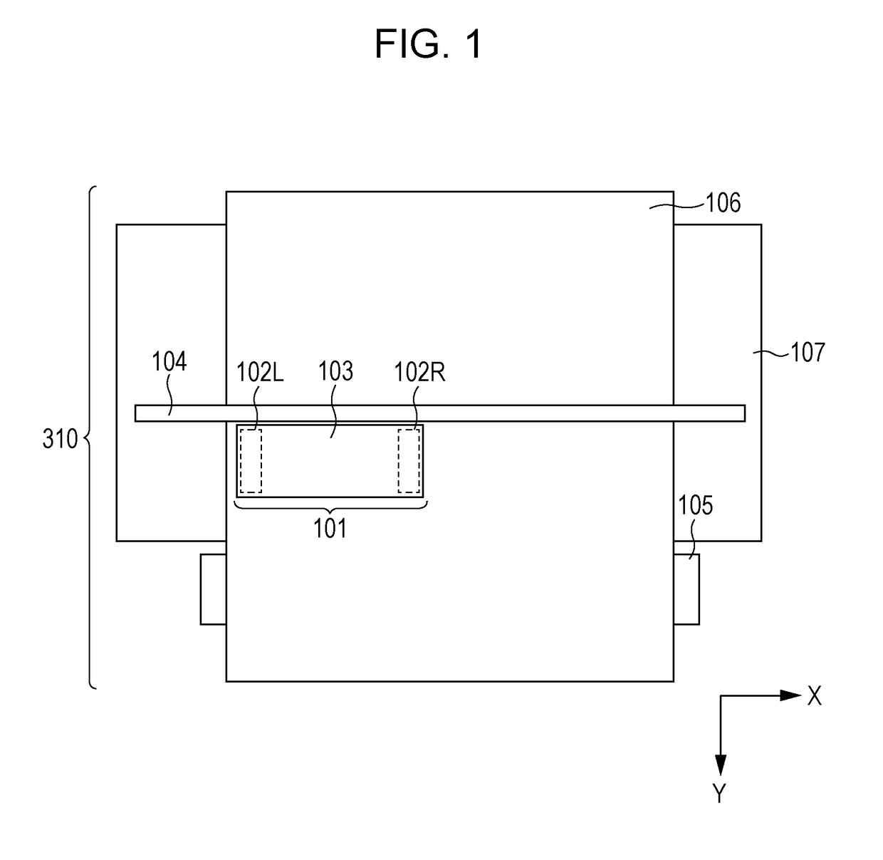
[0036]FIG. 1 is a schematic diagram illustrating an internal configuration of an inkjet recording apparatus 310 according to the present exemplary embodiment.

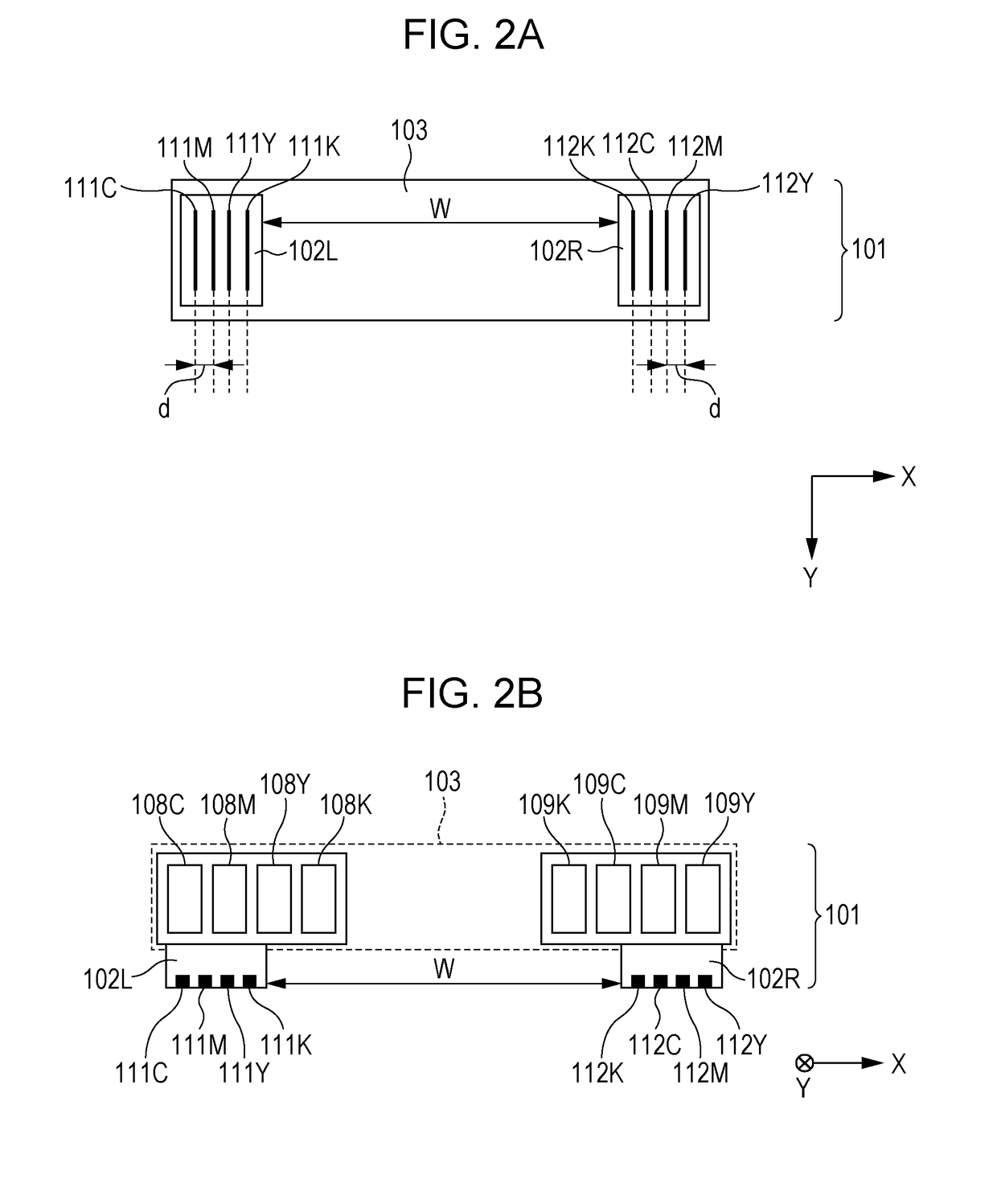
[0037]The inkjet recording apparatus according to the present exemplary embodiment (hereinafter, which will be also referred to as a printer or a recording apparatus) 310 is provided with a recording unit 101. The recording unit 101 includes a recording head 102L and a recording head 102R, and the recording heads 102L and 102R are held by a single holding part 103. Each of the recording heads 102L and 102R is provided with an ejection nozzle array for ejecting black ink, an ejection nozzle array for ejecting cyan ink, an ejection nozzle array for ejecting magenta ink, and an ejection nozzle array for ejecting yellow ink. A detail thereof will be described below.

[0038]The recording unit 101 can rela...

second exemplary embodiment

[0127]According to the present exemplary embodiment, a dither pattern 80 which will be described below is used instead of the dither pattern 70 used according to the first exemplary embodiment, and a dither pattern 81 which will be described below is used instead of the dither pattern 71 to perform the quantization processing. The dither patterns 80 and 81 indicate a spatial frequency characteristic in which the number of low frequency components is low.

[0128]It should be noted that descriptions of parts similar to the above-described first exemplary embodiment will be omitted.

[0129]FIGS. 13A to 13D illustrate the dither pattern 80 used according to the present exemplary embodiment. As illustrated in FIG. 13A, the dither pattern 80 according to the present exemplary embodiment has a size of 512 pixels×512 pixels. It should be noted that, for simplicity, although omitted in FIG. 13A, one of thresholds 1 to 256 is set in each of the pixels having a size of 512 pixels×512 pixels in act...


PUM


Abstract

Quantization is performed on multi-valued data corresponding to a non-overlap recording area and one of recording heads on the basis of a dither pattern and multi-valued data corresponding to the non-overlap recording area and the other one of the recording heads, and also arrangements of thresholds for the dither patterns used between the scanning operations are varied.

Description

BACKGROUND OF THE INVENTIONField of the Invention[0001]The present invention relates to a recording apparatus and a recording method.Description of the Related Art[0002]A recording apparatus has been proposed which records an image by ejecting ink while a recording unit having an ejection nozzle array in which a plurality of ejection nozzles for ejecting the ink are arranged is scanned multiple times with respect to a unit area of a recording medium.[0003]In the above-described recording apparatus, shortening of a recording time with respect to the recording medium has been demanded up to now. To achieve the above-described shortening of the recording time, Japanese Patent Laid-Open No. 10-044519 describes a use of a recording unit including one piece each of a recording unit provided with a plurality of ejection nozzle arrays for ejecting ink of a plurality of colors respectively on a left side and a right side of a scanning direction as the recording unit, According to Japanese Pa...

Claims


Application Information

Patent Timeline
Patent Type & Authority Applications(United States)
IPC IPC(8): B41J2/135H04N1/032H04N1/40
CPCB41J2/135H04N1/0323H04N1/40B41J2/51H04N1/4051
Inventor NAKAGAWA, JUNICHIISHIKAWA, YOSHIKAZUYAMADA, AKITOSHI
Owner CANON KK
Why Eureka
Try Eureka