Sound generating assembly for an exhaust system

a technology of sound generating assembly and exhaust system, which is applied in the direction of sound producing devices, musical instruments, loudspeaker casing supports, etc., can solve the problem of comparatively low manufacturing cost of the sound generating assembly, and achieve the effect of reliable and durable mounting and reliable and durable sound generating assembly

Inactive Publication Date: 2019-03-07
FAURECIA EMISSIONS CONTROL TECH GERMANY
View PDF0 Cites 1 Cited by
  • Summary
  • Abstract
  • Description
  • Claims
  • Application Information

AI Technical Summary

Benefits of technology

[0023]The sound generator housing may be multi-part, and at least one of the brackets, preferably all brackets, may be additionally joined to a sound generator housing part on which the connecting surface is not formed. The latter sound generator housing part may be, for example, a housing rear part or a housing intermediate part. In this context, the housing intermediate part may, for example, carry the sound generator, in particular a loudspeaker. The attachment of the at least one bracket to two sound generator housing parts results in a particularly reliable and durable mounting of the sound generating assembly to the motor vehicle structure.
[0024]According to one variant, as viewed in a sound radiation direction of the sound generator, the connecting surface is arranged at a lateral distance from the sound generator. This distance prevents the sound generator from being impaired in terms of its function and / or service life by installation work done on the connecting surface. In the event that welded joints are arranged on the connecting surface, in this way it is prevented in particular that the sound generator, which may be a loudspeaker, for example, is exposed to excessive temperatures and / or weld spatter. This results in a reliable and durable sound generating assembly.

Problems solved by technology

The coarser tolerancing of the remaining sections of the outer contour, that is, the rest of the outer contour, which usually includes curvatures, rounded portions, and / or similar non-planar sections, results in comparatively low manufacturing costs for the sound generating assembly here.

Method used


Image

  • Sound generating assembly for an exhaust system
  • Sound generating assembly for an exhaust system
  • Sound generating assembly for an exhaust system

Examples


Embodiment Construction

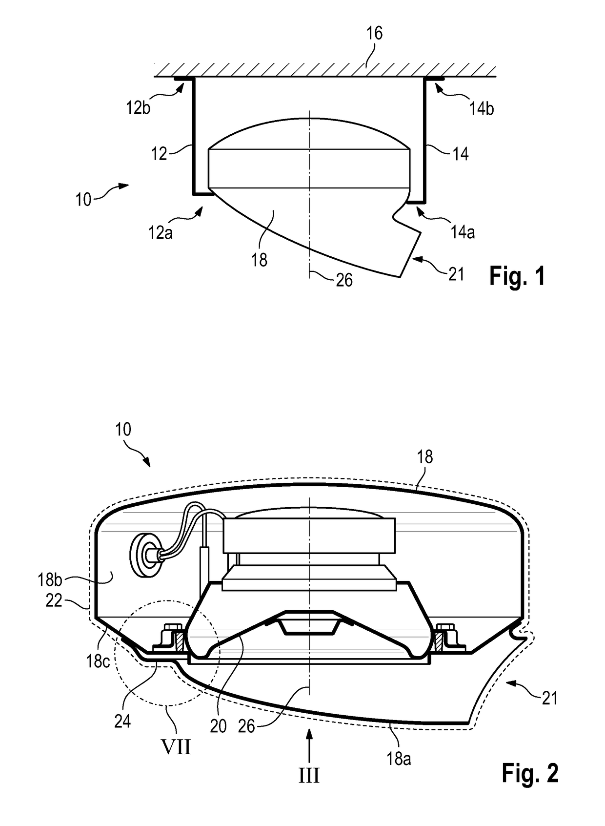
[0033]FIG. 1 shows a sound generating assembly 10 for an exhaust system, not illustrated in more detail, of an internal combustion engine of a motor vehicle.

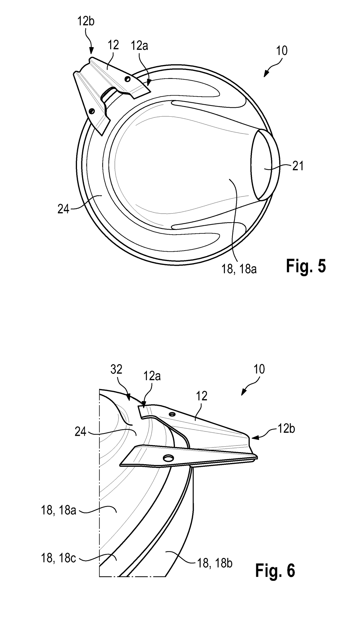
[0034]Here, the sound generating assembly 10 is attached to a motor vehicle structure 16 with two brackets 12, 14, illustrated merely schematically, each of which has a bracket end 12a, 14a on a sound generator housing side and a bracket end 12b, 14b on a motor vehicle structure side.

[0035]The brackets 12, 14 are welded to the sound generating assembly 10; any other suitable joining method may also be used.

[0036]For the connection to the motor vehicle structure 16, any suitable connecting method may be applied.

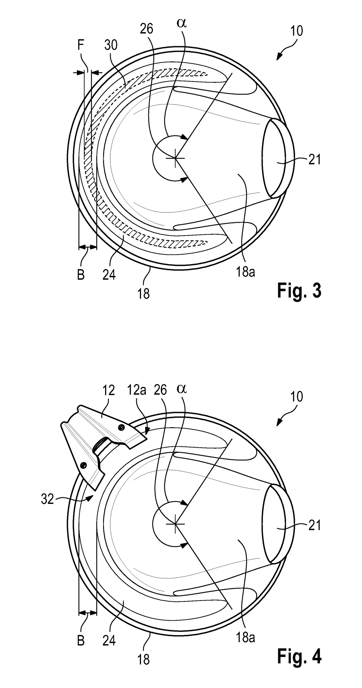
[0037]The sound generating assembly 10 comprises a sound generator housing 18 in which a sound generator 20 is arranged which in the illustrated exemplary embodiment is a loudspeaker (see FIGS. 2 and 7). Sound generated by the sound generator 20 is conducted via a sound outlet opening 21 to an environment or into the exhau...


PUM


Abstract

A sound generating assembly for an exhaust system of an internal combustion engine of a motor vehicle includes a sound generator arranged within a sound generator housing. Furthermore, an outer contour of the sound generator housing has a connecting surface configured to be attached to a motor vehicle structure. The connecting surface is set off from a remaining surface of the outer contour.

Description

CROSS-REFERENCE TO RELATED APPLICATIONS[0001]This application claims priority to DE 10 2017 120 610.8, filed 7 Sep. 2017.FIELD OF INVENTION[0002]The invention relates to a sound generating assembly for an exhaust system of an internal combustion engine of a motor vehicle, which includes a sound generator arranged within a sound generator housing.BACKGROUND OF THE INVENTION[0003]Sound generating assemblies of this kind are known from the prior art and can be subdivided essentially into two groups.[0004]A first group of sound generating assemblies serves to dampen the sound carried by an exhaust gas flow. The sound generating assembly is therefore an active sound absorber. To this end, the sound generated by the sound generating assembly is, ideally, adjusted such that it has a substantially equal amplitude with respect to the sound carried by the exhaust gas flow, but a phase shifted by 180°.[0005]The second group relates to sound generating assemblies which are configured to complem...

Claims


Application Information

Patent Timeline
Patent Type & Authority Applications(United States)
IPC IPC(8): F01N13/08F01N1/06H04R1/02G10K11/178G10K11/00F01N13/18
CPCF01N1/065H04R1/028G10K2210/12822F01N13/08F01N13/1822G10K11/178G10K11/004F01N13/1805H04R9/02H04R9/06F01N13/1855F01N2490/00G10K15/04G10K2210/51H04R1/026
Inventor STEINKILBERG, HANNESHILDEBRAND, MATTHIAS
Owner FAURECIA EMISSIONS CONTROL TECH GERMANY
Why Eureka
Try Eureka