Contact lens inspection system

Active Publication Date: 2019-03-07
ALCON INC
View PDF1 Cites 2 Cited by
  • Summary
  • Abstract
  • Description
  • Claims
  • Application Information

AI Technical Summary

Benefits of technology

The patent is about a new inspection system and method that uses a plenoptic camera to capture images of contact lenses. This system has advantages over conventional cameras because it can refocus on the lens's curved surface, even when it is out of the depth of field. The data from the plenoptic camera can be used to create a final image with a focus plane along the lens's curved surface. This system and method can help improve the inspection process for contact lenses.

Problems solved by technology

However, conventional camera lenses may not be accurate and or / adequate for inspecting curved surfaces such as contact lens surfaces, because, typically, in an inspection system, the object of the image is projected onto a flat CCD image plane.
In specific applications, such as for example, contact lens inspection, reducing the size of the aperture introduces additional difficulties.
Additionally, for items, such as contact lenses, that float in a liquid solution, when the depth of field is adjusted to capture a 3.5 mm depth, the floating debris in solution is also brought into focus, making inspection techniques inaccurate.
On the contrary to conventional cameras, which fail to capture a large amount of optical information, the plenoptic camera captures information about the direction distribution of light rays entering the camera.

Method used


Image

  • Contact lens inspection system
  • Contact lens inspection system
  • Contact lens inspection system

Examples


Embodiment Construction

[0044]The subject matter is now described with reference to the drawings, wherein like reference numerals are used to refer to like elements throughout. In the following description, for purposes of explanation, numerous specific details are set forth in order to provide a thorough understanding of the subject matter. It can be evident, however, that subject matter embodiments can be practiced without these specific details.

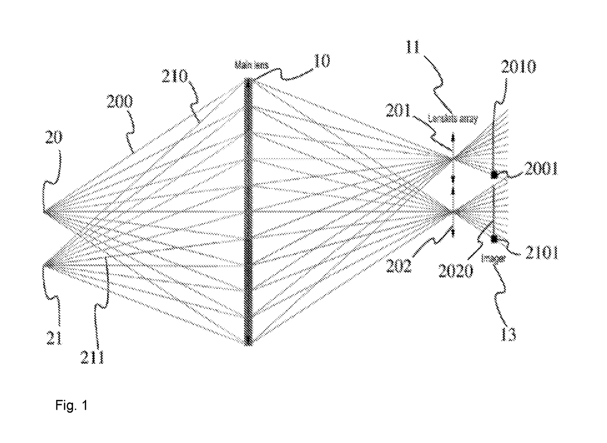
[0045]In contrast to a conventional camera, a “plenoptic” camera samples the four-dimensional (4D) optical phase space or light field and in doing so captures information about the directional distribution of the light rays. An example of such plenoptic camera is described in, R., Levoy, M., Bredif, M., Duval, G., Horowitz, M. and Hanrahan, P., “Light Field Photography with a Hand-Held Plenoptic Camera,” Stanford University Computer Science Tech Report CSTR 2005-02, April 2005. This paper describes plenoptic camera designs based on modifications to a conventional...


PUM


Abstract

A contact lens inspection system, in particular for soft contact lenses, comprises a light source (40) for illuminating a contact lens to be inspected; a plenoptic camera (1) for producing an electronic plenoptic image; a processing unit (103) adapted for electronically processing the electronic plenoptic image of the contact lens and configured for refocusing the image.

Description

BACKGROUNDField of the Invention[0001]The present invention relates to an inspection method and system for contact lenses. More specifically, the present invention relates the design of a “plenoptic” inspection system, which captures information about the direction distribution of light rays entering the camera of the inspection system.Background Art[0002]Cameras and vision systems are often used in inspection systems, particularly to inspect for defects. However, conventional camera lenses may not be accurate and or / adequate for inspecting curved surfaces such as contact lens surfaces, because, typically, in an inspection system, the object of the image is projected onto a flat CCD image plane. A technique used to circumvent this problem is to increase the depth of field of the conventional camera lens by reducing the size of the aperture, while accepting the disadvantages connected with reducing the size of the aperture, such as reduced illumination.[0003]In specific applications,...

Claims


Application Information

Patent Timeline
IPC IPC(8): G01N21/958H04N5/225G06T7/557G06T7/00H04N5/265
CPCG01N21/958H04N5/2256H04N5/22541G06T7/557G06T7/001H04N5/265G01N2021/9583G06T2207/30041G06T2207/20212G06T2207/10052G06T2207/10004G02B27/0075G01M11/0257G01M11/0278H04N23/56H04N23/957
Inventor UNTERKOFLER, SARAHSCHWAB, MATTHIAS
Owner ALCON INC
Why Eureka
Try Eureka