Voice coding apparatus and voice decoding apparatus

A sound coding and coding technology, which is applied in speech analysis, code conversion, signal transmission system, etc., can solve the problem of losing the specialties of algebraic sound source, and achieve the effect of characteristic improvement

Inactive Publication Date: 2004-01-21
MITSUBISHI ELECTRIC CORP
View PDF1 Cites 0 Cited by
  • Summary
  • Abstract
  • Description
  • Claims
  • Application Information

AI Technical Summary

Problems solved by technology

In Japanese Unexamined Patent Publication No. 10-232696, this problem can be solved by having a mode in which the sound source is coded with a random number sequence, etc., but the advantages of an algebraic sound source with a small amount of storage and computation will be lost.

Method used


Image

  • Voice coding apparatus and voice decoding apparatus
  • Voice coding apparatus and voice decoding apparatus
  • Voice coding apparatus and voice decoding apparatus

Examples


Embodiment 1

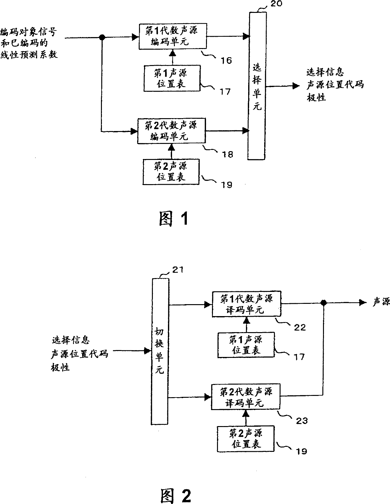
[0072] FIG. 1 shows the configuration of the driving sound source coding unit 5 of the speech coding apparatus of the present invention. The general structure of the audio coding device is the same as that in Fig.15. In the figure, 16 is a first algebraic sound source coding unit, 17 is a first sound source position table, 18 is a second algebraic sound source coding unit, 19 is a second sound source position table, and 20 is a selection unit.

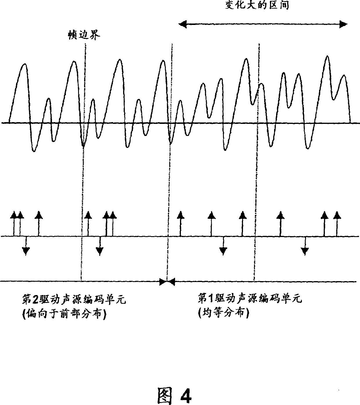
[0073] The first sound source position table 17 has a uniform position distribution in the frame, and the second sound source position table 19 has a position distribution in the first half of the frame.

[0074] FIG. 2 shows the structure of the drive excitation decoding unit 12 of the audio decoding device of the present invention. The general structure of the audio decoding device is the same as that in Fig.16. In the figure, 21 is a switching unit, 22 is a first algebraic excitation decoding unit, and 23 is a second algebraic exc...

Embodiment 2

[0100] Fig. 5 is a diagram showing another example of the sound source position table used when the frame length of the sound source coding is 80 points.

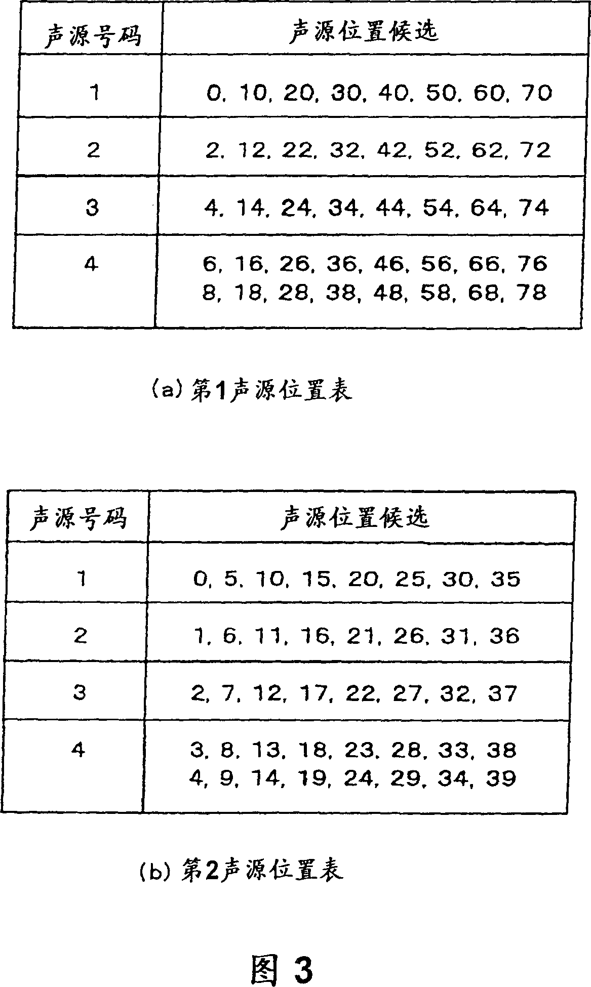
[0101] FIG. 5( a ) is the first sound source position table 17 , and FIG. 5( b ) is the second sound source position table 19 . The first sound source position table 17 is the same as FIG. 3( a ), and is twice the sound source position in the sound source position table of Document 1 shown in FIG. 17 . That is, sound source position candidates are set every other sample. On the contrary, in the second sound source position table 19, 40 is added to each position value in the sound source position table of Document 1 shown in FIG. 17 . As a result, only the positions in the second half of the sound source frame are set as sound source position candidates. That is, no sound source position candidates are set for the first half of the sound source frame.

[0102] The configurations of driving excitation encoding section 5 an...

Embodiment 3

[0113] FIG. 7 shows the configuration of the driving sound source encoding unit 5 of the audio encoding device of the present invention. The general structure of the audio coding device is the same as that in Fig.15. In the figure, 16 is the first algebraic sound source coding unit, 17 is the first sound source position table, 18 is the second algebraic sound source coding unit, 19 is the second sound source position table, 24 is the judgment unit, and 25 is the selection unit .

[0114] FIG. 8 shows the structure of the drive excitation decoding unit 12 of the audio decoding device of the present invention. The overall structure of the audio decoding device is the same as that in FIG. 16 , the only difference is that the output of the linear prediction coefficient decoding unit 10 is supplied to the driving excitation decoding unit 5 and also to the driving excitation decoding unit 12 . In the figure, 26 is a switching unit, 22 is a second algebraic excitation decoding unit...


PUM


Abstract

Drive sound source coding means, decoding means has a plurality of algebraic sound source coding means, decoding means having sound source position tables different in distribution lean of sound source position candidates in a frame, each algebraic sound source coding means, decoding means for referencing spectrum envelope information and coding the sound source of an input voice based on a sound source position selected from among the sound source position candidates in the sound source position table and a polarity and selection means for selecting the algebraic sound source coding means, decoding means with the smallest coding distortion from among the plurality of algebraic sound source coding means, decoding means and outputting code representing the drive sound source position output by the selected algebraic sound source coding means, and polarity.

Description

technical field [0001] The present invention relates to an audio coding device for compressing a digital audio signal into a small amount of information, and an audio decoding device for reproducing a digital audio signal after decoding an audio code generated by the audio encoding device or the like. Background technique [0002] In many existing sound coding devices and sound decoding devices, the input sound is divided into spectrum envelope information and sound source, and they are encoded in frame units to generate sound codes. After decoding the sound codes, use The synthesis filter combines the spectral envelope information with the sound source to obtain the structure of the decoded sound. [0003] As the most representative audio coding apparatus and audio decoding apparatus, there is an apparatus using a code-excited linear prediction coding (Code-Excited Linear Prediction: CELP) method. [0004] Fig. 15 is a diagram showing the general configuration of a convent...

Claims


Application Information

Patent Timeline
Patent Type & Authority Patents(China)
IPC IPC(8): G10L19/08G10L19/04G10L19/107H03M7/34
CPCG10L19/10G10L2019/0008
Inventor 田崎裕久山浦正
Owner MITSUBISHI ELECTRIC CORP
Why Eureka
Try Eureka