Eureka AIR delivers breakthrough ideas for toughest innovation challenges, trusted by R&D personnel around the world.

Speed of sound and/or density measurement using acoustic impedance

a technology of acoustic impedance and speed of sound, applied in the direction of instruments, specific gravity measurement, measurement devices, etc., can solve the problems of reducing strength, direct use of density measurement, and current methods for measuring entrapped air can be slow and cumbersom

Pending Publication Date: 2019-03-07
CIDRA CORP SERVICES
View PDF7 Cites 2 Cited by
  • Summary
  • Abstract
  • Description
  • Claims
  • Application Information

AI Technical Summary

Benefits of technology

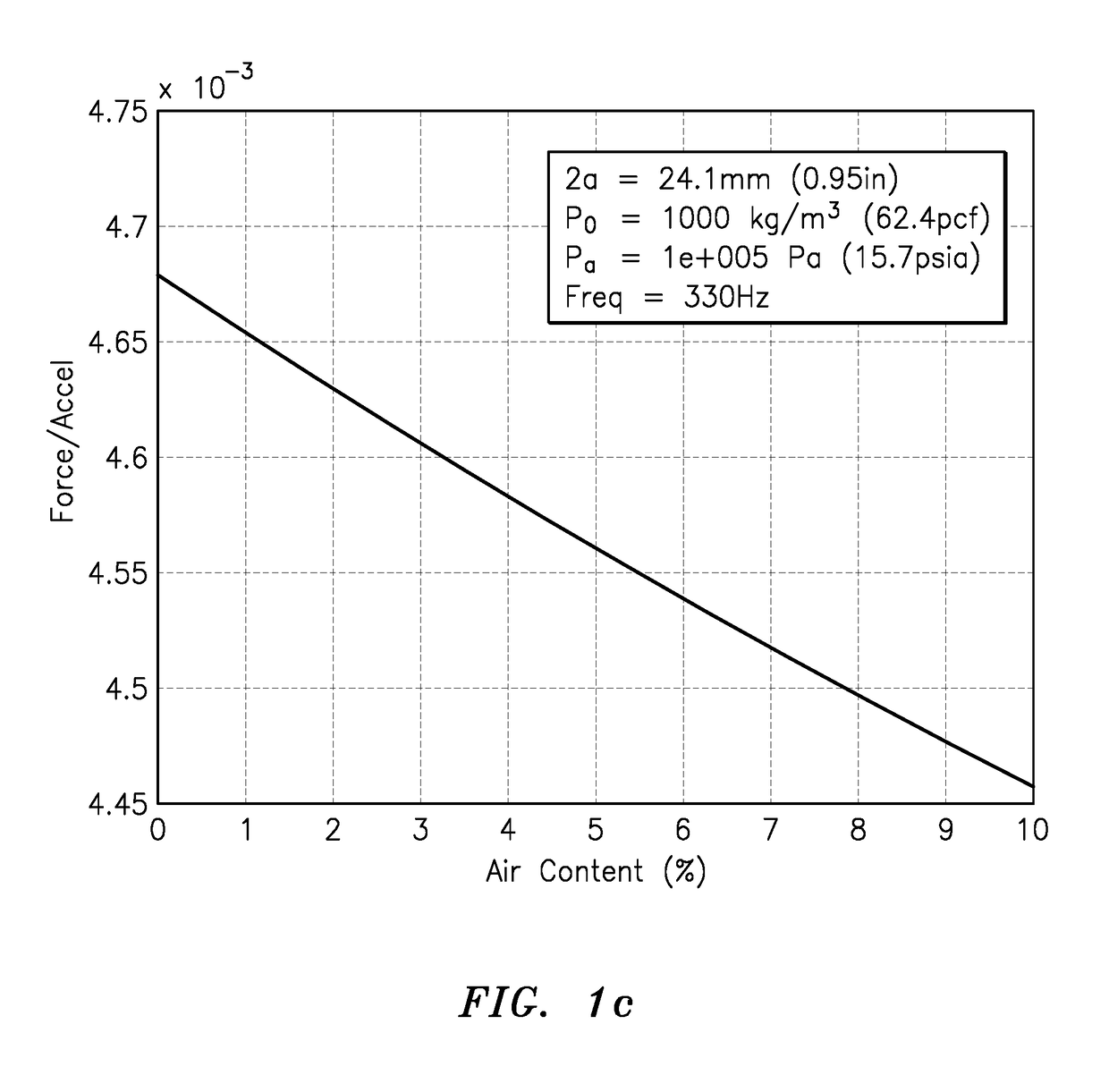
The present invention provides a new technique for measuring the speed of sound and density of a fluid or slurry by measuring the acoustic reaction force on a vibrating piston. This can be useful in many industrial processes to determine the volume percent of air in the process. The invention includes a signal processor or signal processing module that receives information about the radiation impedance of the piston and determines the speed of sound or density measurement related to the process medium, based on the signaling received. The invention can be used in processes such as concrete manufacturing, where the speed of sound measurement can be used to determine the volume percent of air in the process. The invention includes a transducer apparatus or device that vibrates the process medium and acts as an acoustic source. The invention can be used in various processing containers or pipes to measure the density of the process flow fluid / slurry.

Problems solved by technology

While the measurement of the speed of sound (SOS) in a fluid can be used to give a measure of the constituents of a flow (for example oil-water in an oil production application), it's direct use for density measurement is limited unless there is a priori knowledge of the density of the component constituents (or “phases”) of the process flow stream.
However, the entrained air in concrete has the disadvantage of reducing strength so there is always a trade-off to determine the right amount of air for a particular application.
Current methods for measuring the entrained air can sometimes be slow and cumbersome and additionally can be prone to errors.
Too little entrained air reduces the durability of the concrete and too much entrained air decreases the strength.

Method used


Image

  • Speed of sound and/or density measurement using acoustic impedance
  • Speed of sound and/or density measurement using acoustic impedance
  • Speed of sound and/or density measurement using acoustic impedance

Examples


Embodiment Construction

CCS-0084: FIGS. 1a-1d

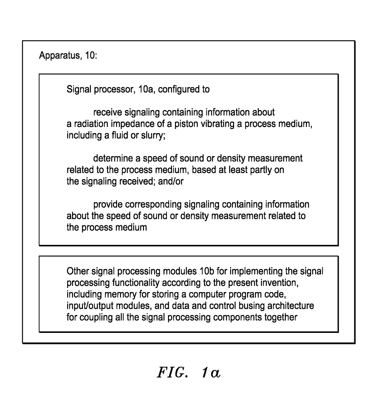
[0069]FIG. 1a shows apparatus generally indicated as 10 according to some embodiments of the present invention. The apparatus 10 may include a signal processor or signal processing module 10a configured to receive signaling containing information about a radiation impedance of a piston vibrating a process medium, including a fluid or slurry; and determine a speed of sound or density measurement related to the process medium, based at least partly on the signaling received.

[0070]The signal processor or signal processing module 10a may also be configured to providing corresponding signaling containing information about the speed of sound or density measurement related to the process medium.

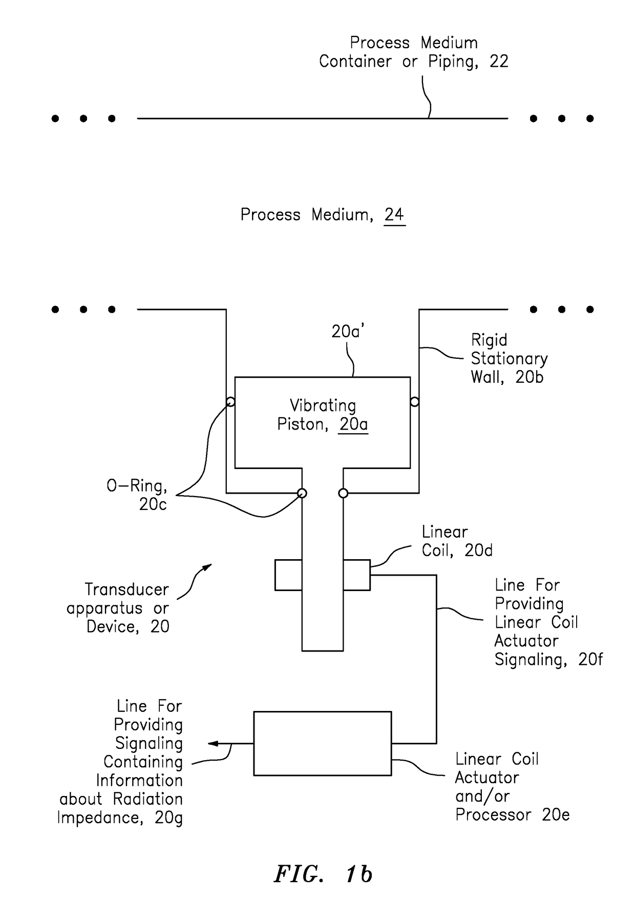
[0071]By way of example, a person skilled in the art would appreciate that radiation impedance may be understood to mean, or may be defined as, the ratio of the force a radiator exerts on a process flow medium to the velocity of the radiator.

FIG. 1b: The Vibrating Piston

[0072]B...


PUM

PropertyMeasurementUnit
displacementaaaaaaaaaa
compressibilityaaaaaaaaaa
1/βaaaaaaaaaa

Abstract

Apparatus is provided featuring a signal processor or signal processing module configured at least to: receive signaling containing information about a radiation impedance of a piston vibrating a process medium, including a fluid or slurry; and determine a speed of sound or density measurement related to the process medium, based at least partly on the signaling received. The signal processor or signal processing module may determine a speed of sound measurement related to the process medium, based on at least partly on the density of the process medium, including where the density of the process medium is known, assumed or determined by the signal processor or signal processing module, or determine a density measurement related to the process medium, based on at least partly on the speed at which sound travels in the process medium, including where the speed of sound of the process medium is known, assumed or determined by the signal processor or signal processing module.

Description

CROSS-REFERENCE TO RELATED APPLICATIONS[0001]This application claims benefit to provisional patent application Ser. No. 61 / 620,788, filed 5 Apr. 2012 (WFVA / CiDRA file nos. 712-2.380), entitled “Speed of sound and / or density measurement using acoustic impedance;” and Ser. No. 61 / 658,628, filed 12 Jun. 2012 (WFVA / CiDRA file nos. 712-2.390), entitled “Determination of the density of a process flow fluid / slurry using both speed of sound and fluid compressibility measurements,” which are both incorporated by reference in their entirety.[0002]This application also relates to U.S. patent application Ser. No. 13 / 583,062, filed 12 Sep. 2012 (WFVA / CiDRA file nos. 712-2.338-1 / CCS-0033, 35,40, and 45-49), which is a national stage application corresponding to PCT / US11 / 27731, which are both incorporated in their entirety by reference, and assigned to the assignee of the present application.[0003]This application also relates to Patent Cooperation Treaty application serial no. PCT / US12 / 60822, fil...

Claims


Application Information

Patent Timeline
Patent Type & Authority Applications(United States)
IPC IPC(8): G01N29/028G01N33/38
CPCG01N2291/0251G01N29/028G01N33/383G01N29/024G01N9/24G01N2291/02416G01N2291/02818
Inventor LOOSE, DOUGLAS H.DIDDEN, LAMBERTUS J.KERSEY, ALAN D.
Owner CIDRA CORP SERVICES
Why Eureka
Eureka Blog
Learn More