
Systems, methods, and devices for automatic signal detection based on power distribution by frequency over time within a spectrum

a technology of automatic signal detection and power distribution, applied in the field of radio frequency (rf) signal spectrum analysis and management, can solve the problems of increasing spectrum need despite, difficult to obtain effective spectrum management, and complicated changes in software and hardware for narrowly tailored devices

Active Publication Date: 2019-03-07
DIGITAL GLOBAL SYST INC
View PDF0 Cites 45 Cited by
  • Summary
  • Abstract
  • Description
  • Claims
  • Application Information

AI Technical Summary

Benefits of technology

The invention is about a system, method and device that can detect signals in an RF environment and extract temporary features from them. This allows the device to automatically detect signals that are low power or narrowband, which might be difficult to identify other ways.

Problems solved by technology

A problem faced in effective spectrum management is the various numbers of devices emanating wireless signal propagations at different frequencies and across different technological standards.
Coupled with the different regulations relating to spectrum usage around the globe effective spectrum management becomes difficult to obtain and at best can only be reached over a long period of time.
Another problem facing effective spectrum management is the growing need from spectrum despite the finite amount of spectrum available.
Problems arise with these narrowly tailored devices as cellular standards change and / or spectrum use changes impact the spectrum space of these technologies.
Changes to the software and hardware for these narrowly tailored devices become too complicated, thus necessitating the need to purchase a totally different and new device.
Unfortunately, this type of device is only for a specific use and cannot be used to alleviate the entire needs of the spectrum management community.
The second type of spectral management device employs a methodology that requires bulky, extremely difficult to use processes, and expensive equipment.
In order to attain a broad spectrum management view and complete all the necessary tasks, the device ends up becoming a conglomerate of software and hardware devices that is both hard to use and difficult to maneuver from one location to another.
While there may be several additional problems associated with current spectrum management devices, at least four major problems exist overall: 1) most devices are built to inherently only handle specific spectrum technologies such as 900 MHz cellular spectrum while not being able to mitigate other technologies that may be interfering or competing with that spectrum, 2) the other spectrum management devices consist of large spectrum analyzers, database systems, and spectrum management software that is expensive, too bulky, and too difficult to manage for a user's basic needs, 3) other spectrum management devices in the prior art require external connectivity to remote databases to perform analysis and provide results or reports with analytics to aid in management of spectrum and / or devices, and 4) other devices of the prior art do not function to provide real-time or near real-time data and analysis to allow for efficient management of the space and / or devices and signals therein.
In today's complex RF environment, to detect a signal can be difficult, especially for those that are less consistent, with low power levels, or buried in easily identified signals.
These signals cannot be detected by a radio gear in the prior art.
However, these devices cannot detect signals that are not in the external database.

Method used


Image

  • Systems, methods, and devices for automatic signal detection based on power distribution by frequency over time within a spectrum
  • Systems, methods, and devices for automatic signal detection based on power distribution by frequency over time within a spectrum
  • Systems, methods, and devices for automatic signal detection based on power distribution by frequency over time within a spectrum

Examples


Embodiment Construction

[0127]Related US patents and patent applications include U.S. application Ser. No. 15 / 357,157, U.S. Pat. No. 9,537,586, U.S. Pat. No. 9,185,591, U.S. Pat. No. 8,977,212, U.S. Pat. No. 8,798,548, U.S. Pat. No. 8,805,291, U.S. Pat. No. 8,780,968, U.S. Pat. No. 8,824,536, U.S. Pat. No. 9,288,683, U.S. Pat.No. 9,078,162, U.S. application Ser. No. 13 / 913,013, and U.S. Application No. 61 / 789,758. All of them are incorporated herein by reference in their entirety.

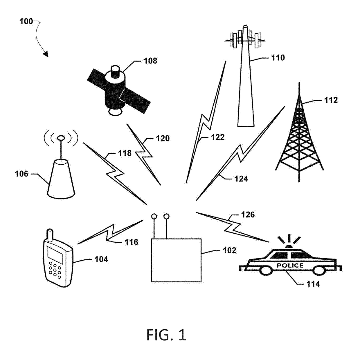
[0128]The present invention addresses the longstanding, unmet needs existing in the prior art and commercial sectors to provide solutions to the at least four major problems existing before the present invention, each one that requires near real time results on a continuous scanning of the target environment for the spectrum.

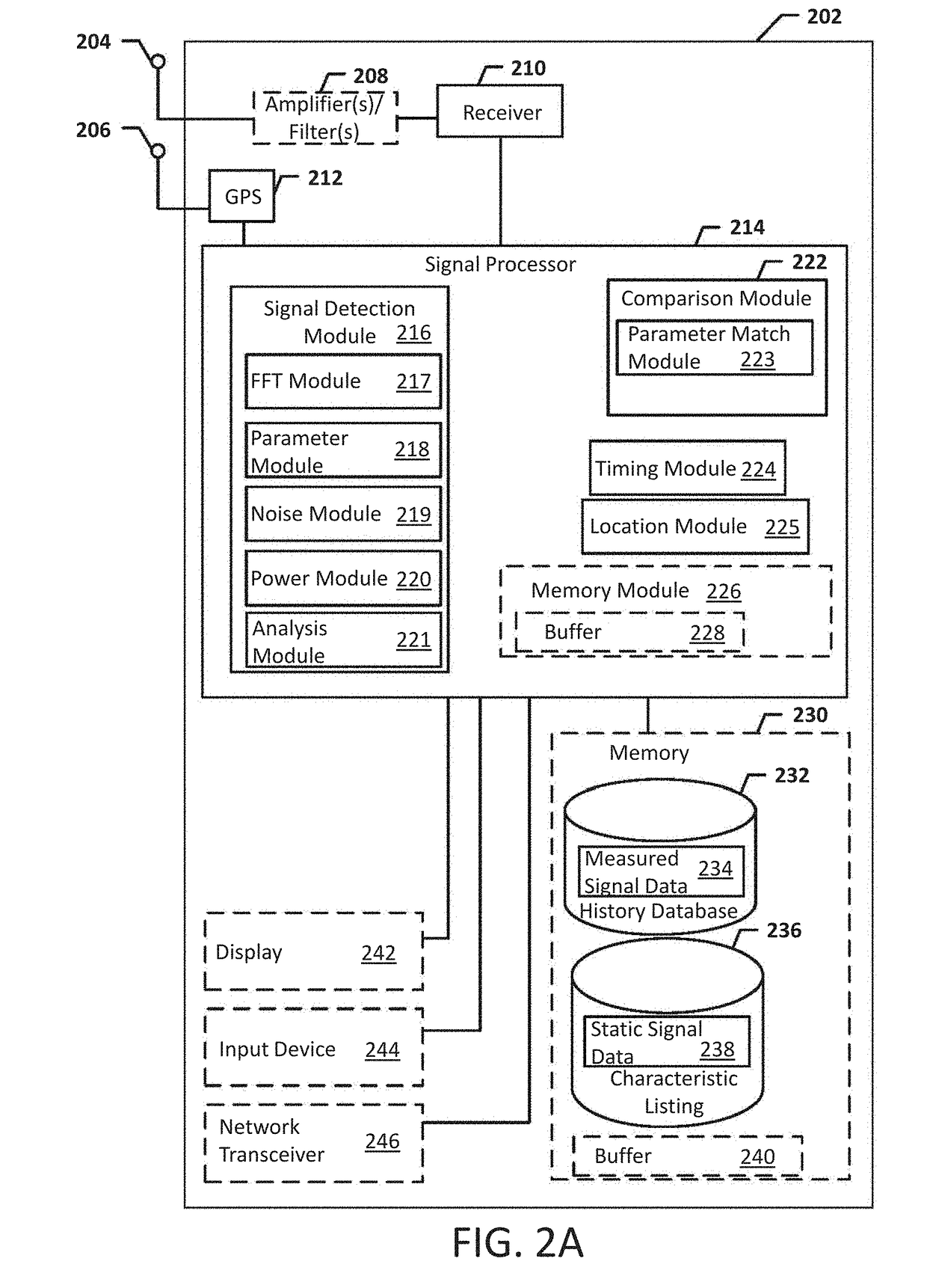
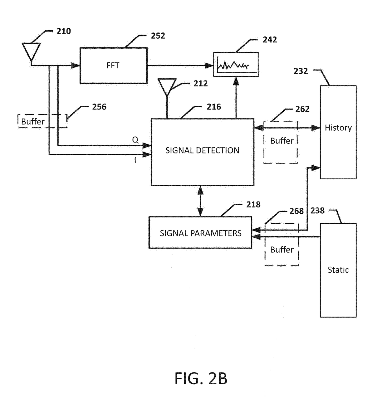
[0129]The present invention relates to systems, methods, and devices of the various embodiments enable spectrum management by identifying, classifying, and cataloging signals of interest based on radio frequen...


PUM


Abstract

Systems, methods and apparatus for automatic alarm management in a radio-frequency (RF) environment are disclosed. An apparatus calculates a power distribution by frequency of the RF environment in real time or near real time, including a first derivative and a second derivative of FFT data of the RF environment. The apparatus then creates a baseline based on the power distribution by frequency of the RF environment in a period of time, identifies at least one alarm situation based on a multiplicity of alarm triggering conditions by comparing the power distribution in real time or near real time to the baseline of the RF environment, identifies at least one signal based on the first derivative and the second derivative of FFT data in the at least one alarm situation, and sends at least one alarm comprising details of the at least one signal identified in the at least one alarm situation.

Description

CROSS-REFERENCE TO RELATED APPLICATIONS[0001]This application relates to and claims priority from the following applications. This application is a continuation-in-part of U.S. patent application Ser. No. 15 / 412,982 filed Jan. 23, 2017. This application also claims priority from U.S. Provisional Patent Application No. 62 / 722,420 filed Aug. 24, 2018. Each of the above-mentioned documents is incorporated herein in their entirety.BACKGROUND OF THE INVENTION1. Field of the Invention[0002]The present invention relates to spectrum analysis and management for radio frequency (RF) signals, and more particularly for automatically identifying signals in a wireless communications spectrum based on temporal feature extraction.2. Description of the Prior Art[0003]Generally, it is known in the prior art to provide wireless communications spectrum management for detecting devices for managing the space. Spectrum management includes the process of regulating the use of radio frequencies to promote ...

Claims


Application Information

Patent Timeline
Patent Type & Authority Applications(United States)
IPC IPC(8): G01R29/08G08B21/18
CPCG01R29/0892G08B21/18G08B29/185
Inventor DZIERWA, RONALD C.KLEINBECK, DAVID WILLIAM
Owner DIGITAL GLOBAL SYST INC
Learn More