Optical element and display device

a display device and optical element technology, applied in the field of optical elements and display devices, can solve the problems of drastic reduction of image resolution in the majority of near-eye light field displays, and achieve the effect of improving the resolution capability of existing display devices and improving high-resolution images

Active Publication Date: 2019-03-07
CORETRONIC
View PDF4 Cites 1 Cited by
  • Summary
  • Abstract
  • Description
  • Claims
  • Application Information

AI Technical Summary

Benefits of technology

[0006]The invention provides an optical element and a display device which can improve resolution capability of existing display devices. Through a space division multiplexing architecture of the invention, a viewer may see an original low-resolution image at different times to get an improved high-resolution image.

Problems solved by technology

Thus, most near-eye light field displays have a problem of drastic reduction in image resolution.
Therefore, how to effectively improve the image resolution of the current near-eye light field displays or general near-eye displays is one of the issues that receive attention of people in this field.

Method used


Image

  • Optical element and display device
  • Optical element and display device
  • Optical element and display device

Examples


Embodiment Construction

[0017]In the following detailed description of the preferred embodiments, reference is made to the accompanying drawings which form a part hereof, and in which are shown by way of illustration specific embodiments in which the invention may be practiced. In this regard, directional terminology, such as “top,”“bottom,”“front,”“back,” etc., is used with reference to the orientation of the Figure(s) being described. The components of the present invention can be positioned in a number of different orientations. As such, the directional terminology is used for purposes of illustration and is in no way limiting. On the other hand, the drawings are only schematic and the sizes of components may be exaggerated for clarity. It is to be understood that other embodiments may be utilized and structural changes may be made without departing from the scope of the present invention. Also, it is to be understood that the phraseology and terminology used herein are for the purpose of description an...


PUM

PropertyMeasurementUnit
angleaaaaaaaaaa
frequencyaaaaaaaaaa
thicknessaaaaaaaaaa

Abstract

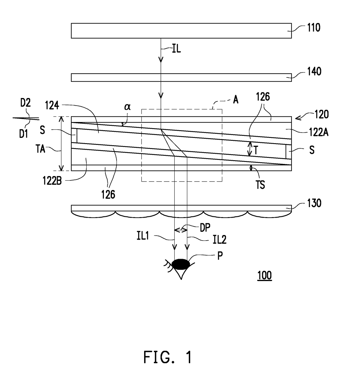
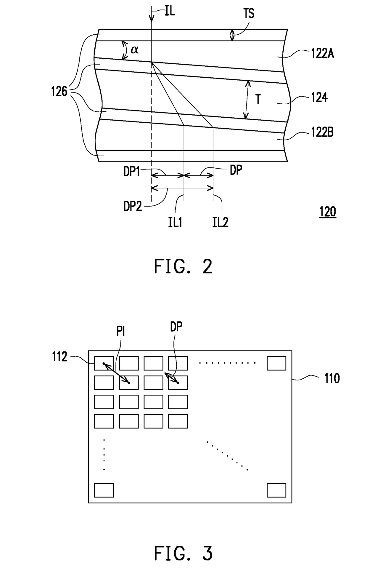
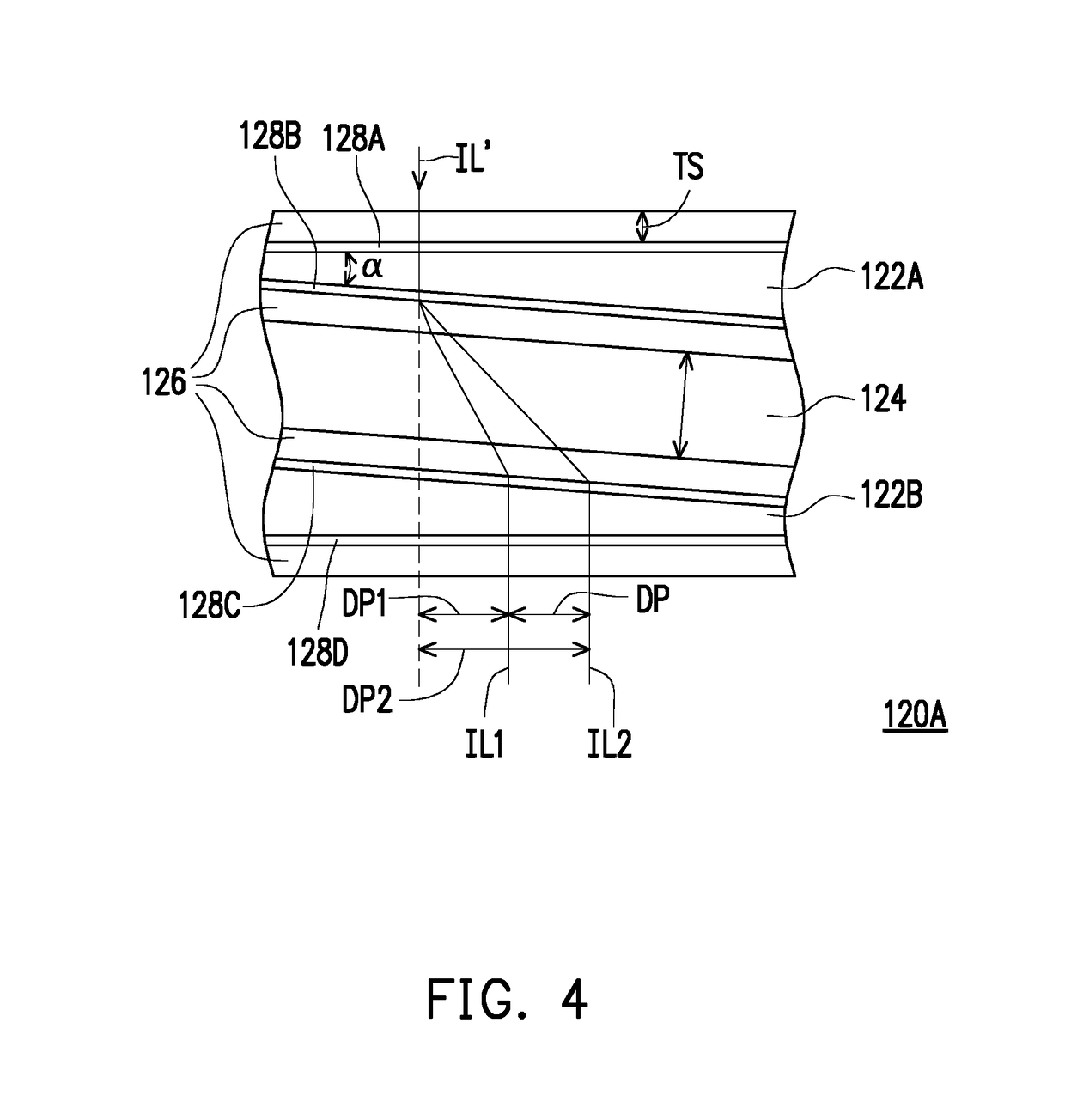
An optical element configured to allow an image beam passing through is provided. The optical element includes a first and a second birefringent layer and a gas layer between the first and the second birefringent layer. An extension direction of the gas layer is inclined with respect to an extension direction of the optical element, wherein the image beam passes through the first birefringent layer, the gas layer and the second birefringent layer in sequence. A first and a second sub image beam having different deflection angles are generated from the image beam when the image beam enters the gas layer. After the first and the second sub image beam are emitted from the second birefringent layer, a transmission path of the first and the second sub image beam are offset from each other by an offset distance, thereby improving resolution of an image to be viewed.

Description

CROSS-REFERENCE TO RELATED APPLICATION[0001]This application claims the priority benefit of China application serial no. 201710798903.2, filed on Sep. 7, 2017. The entirety of the above-mentioned patent application is hereby incorporated by reference herein and made a part of this specification.BACKGROUNDField of the Invention[0002]The invention relates to an optical element and a display device, particularly to a near-eye display for displaying two-dimensional information or three-dimensional information and an optical element for a near-eye display.Description of Related Art[0003]With rapid development of near-eye displays (NEDs), in order to allow a user to see a more realistic image and enjoy a more comfortable visual effect when wearing the near-eye display, near-eye light field displays have been launched. A major difference between the near-eye light field displays and traditional near-eye displays lies in that, through a light field imaging mechanism, the near-eye light fiel...

Claims


Application Information

Patent Timeline
Patent Type & Authority Applications(United States)
IPC IPC(8): G02F1/1347G02F1/1343G02B30/25
CPCG02F1/13471G02F1/13439G02F2203/50G02B27/0101G02F1/133371G02F1/29G02F1/0322G02B30/24G02B30/25
Inventor HUANG, YI-PAIJEN, TAI-HSIANGHSIEH, PO-YUANWU, JUI-YICHUANG, FU-MING
Owner CORETRONIC
Why Eureka
Try Eureka