
Keyboard apparatus

a keyboard and key technology, applied in the field of keyboard apparatus, can solve the problems of increased manufacturing costs of the keyboard itself, inconvenience in actual assembly, and prone to ghost key phenomenon, and achieve the effect of reducing manufacturing costs

Inactive Publication Date: 2019-03-07
LITE ON ELECTRONICS (GUANGZHOU) LTD +1
View PDF7 Cites 1 Cited by
  • Summary
  • Abstract
  • Description
  • Claims
  • Application Information

AI Technical Summary

Benefits of technology

The invention is about a new kind of keyboard that stops people from hitting keys on other parts of the keyboard (known as ghosting). It's cheaper than existing solutions too.

Problems solved by technology

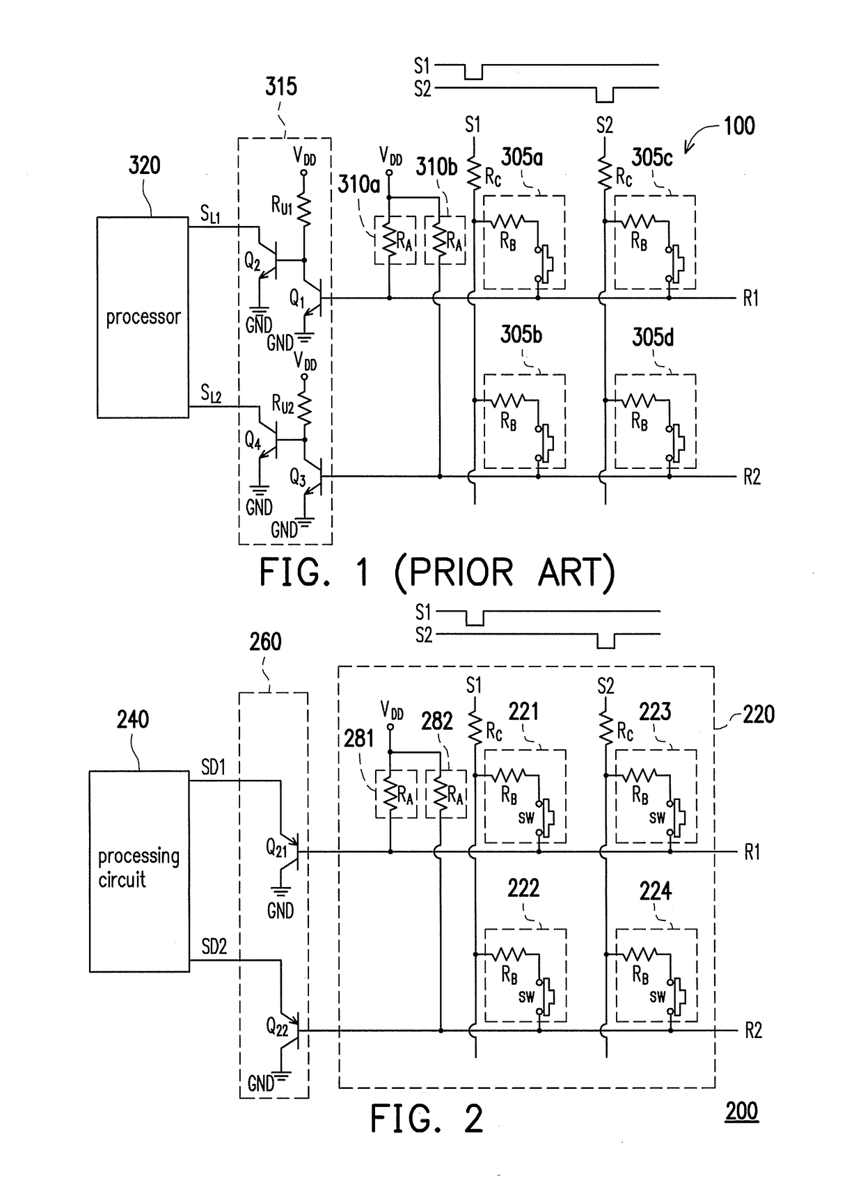
The technical problem addressed in this patent text is how to prevent the occurrence of ghost key phenomenon in a keyboard apparatus without significantly increasing manufacturing costs. The conventional method of using a level detection circuit with two transistors and one resistor to detect the pressing of keys on a return line results in a high number of components and increased manufacturing costs. The patent proposes a new solution to reduce manufacturing costs without compromising the effectiveness of the level detection circuit.

Method used


Image

  • Keyboard apparatus
  • Keyboard apparatus
  • Keyboard apparatus

Examples


Embodiment Construction

[0028]Descriptions of the disclosure are given with reference to the exemplary embodiments illustrated by the accompanying drawings. In addition, wherever possible, identical or similar reference numerals stand for identical or similar elements / components in the drawings and embodiments.

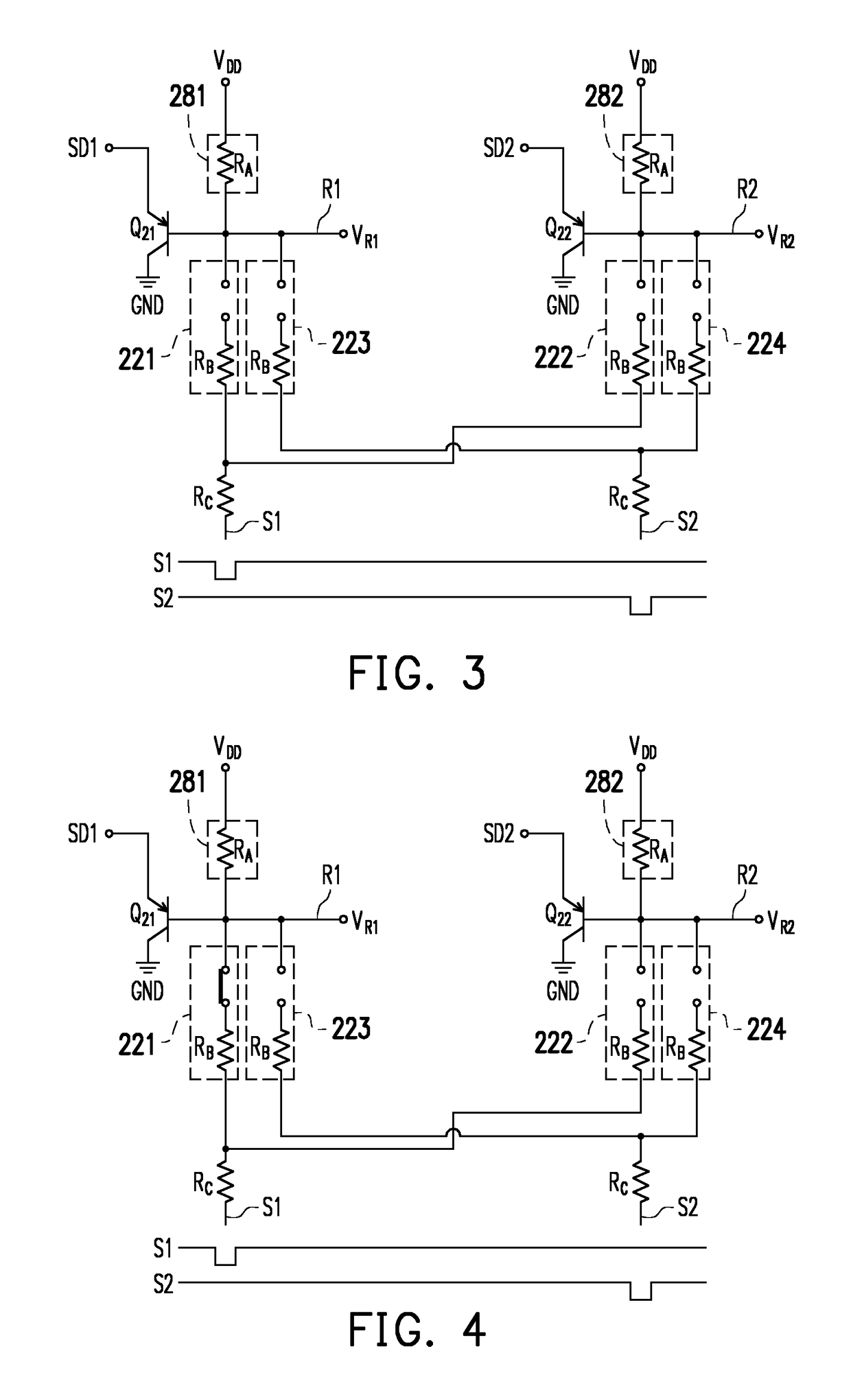
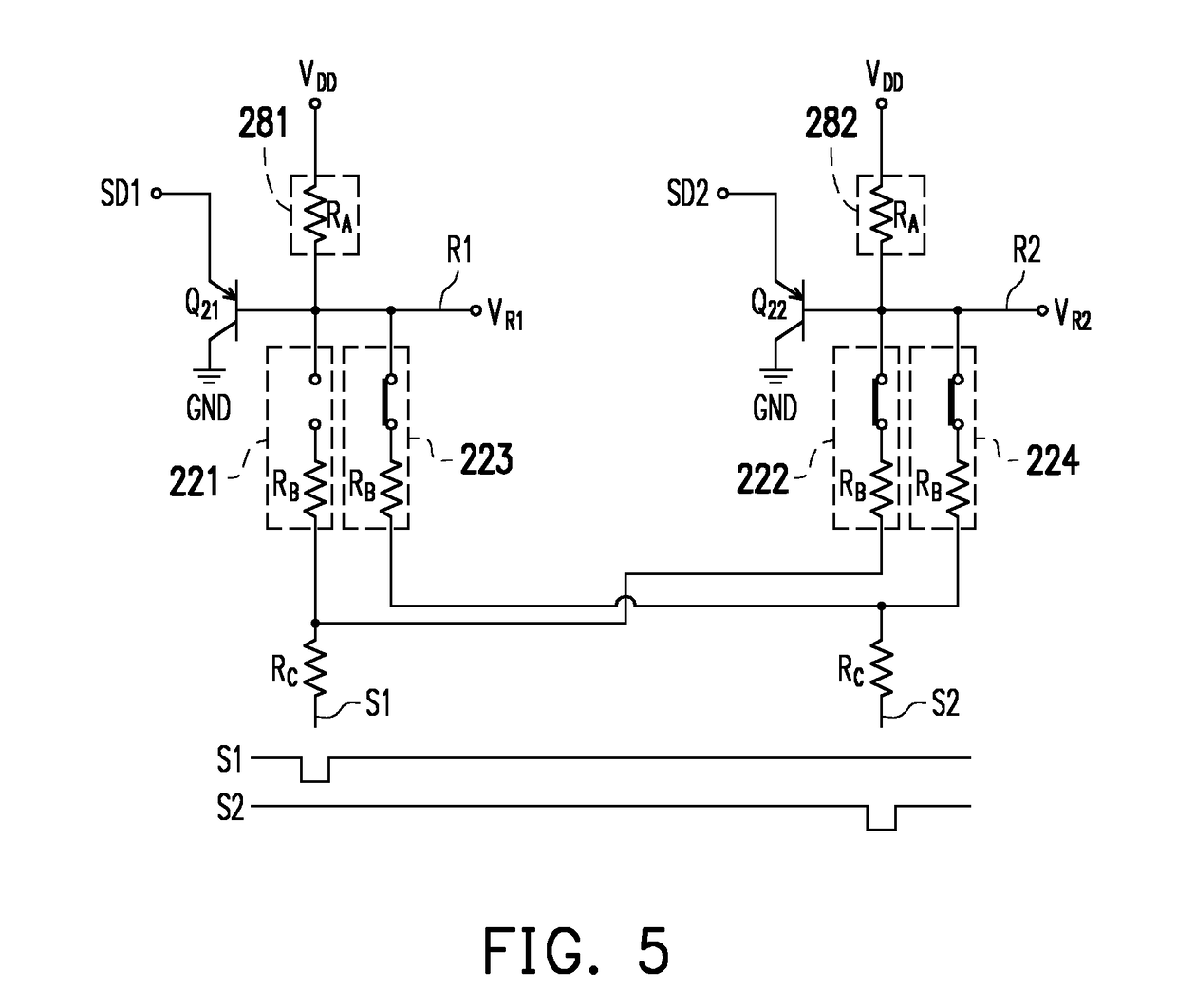
[0029]Hereinafter, with reference to FIG. 2, FIG. 2 is a schematic view showing a keyboard apparatus 200 according to an embodiment of the disclosure. The keyboard apparatus 200 includes a key module 220, a detection circuit 260 and a processing circuit 240, but the disclosure is not limited thereto. The key module 220 includes (M×N) keys, N scan lines and M return lines, wherein M may be a positive integer greater than or equal to 2, and N may also be a positive integer greater than or equal to 2. However, for the convenience of illustration, in this embodiment, it is assumed that M and N are both 2, and embodiments where M and N are other numerals may be inferred from the following description. Con...


PUM


Abstract

A keyboard apparatus including a key module and a detection circuit is provided. The key module includes a plurality of keys, a plurality of scan lines and a plurality of return lines. The scan lines and the return lines are crossed to each other and respectively coupled to the keys. The detection circuit detects a plurality of return voltages of the return lines and generates a plurality of detection signals accordingly so as to indicate that a switch of each of the keys is at an on state or at an off state. The detection circuit includes a plurality of P-type transistors. A first terminal of each P-type transistor is coupled to a ground terminal, a control terminal of each P-type transistor is directly coupled to a corresponding one of the return lines, and a second terminal of each P-type transistor generates and outputs one of the detection signals.

Description


Claims


Application Information

Patent Timeline
Owner LITE ON ELECTRONICS (GUANGZHOU) LTD
Learn More