
Laser processing apparatus

Inactive Publication Date: 2019-03-14
DISCO CORP
View PDF0 Cites 0 Cited by
  • Summary
  • Abstract
  • Description
  • Claims
  • Application Information

AI Technical Summary

Benefits of technology

The present invention provides a laser processing apparatus that can apply a pulsed laser beam to different areas of a workpiece, resulting in better processing quality. This is achieved by using a laser oscillator, a polygon mirror, and a condenser to disperse the laser beam and apply it to the workpiece. The dispersed region adjusting means controls the direction in which the mirror facets of the polygon mirror are rotated, causing the laser beam to follow a specific path. This allows for precise and effective laser processing.

Problems solved by technology

However, the laser processing apparatus disclosed in Japanese Patent No. 4044539 is problematic in that since a pulsed laser beam is dispersed over a region established by the polygon mirror and applied to a workpiece, the pulsed laser beam cannot be dispersed over an appropriate region depending on the workpiece, with the result that a processed quality depending on the workpiece cannot be achieved.

Method used


Image

  • Laser processing apparatus
  • Laser processing apparatus
  • Laser processing apparatus

Examples


Embodiment Construction

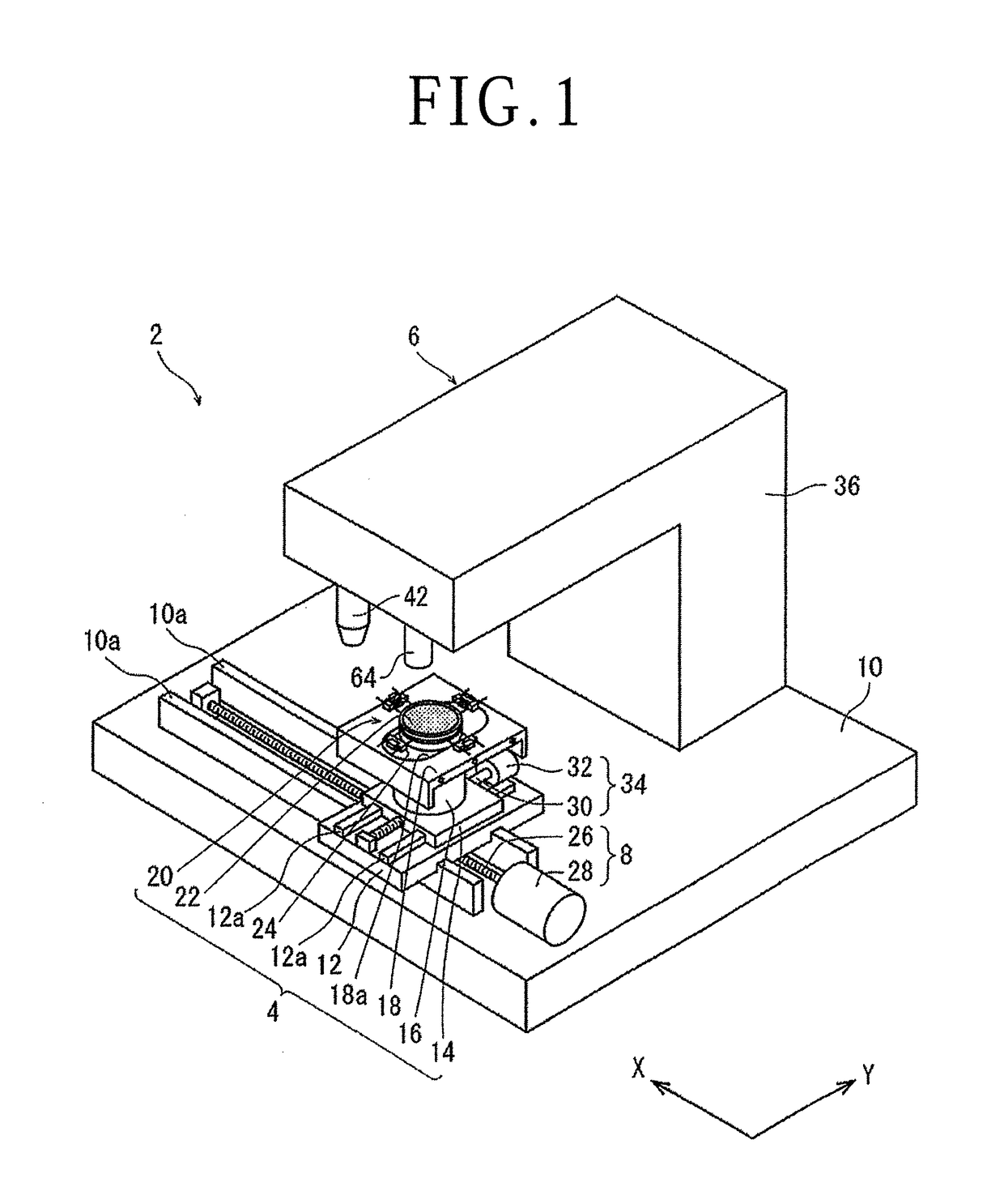
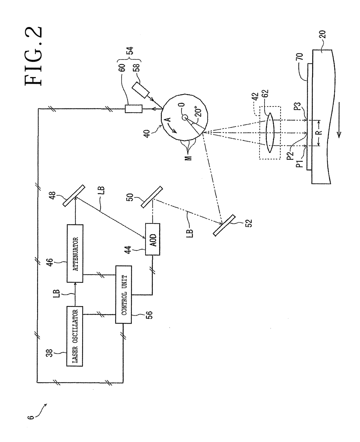
[0016]A laser processing apparatus according to an embodiment of the present invention will be described in detail below with reference to the drawings. As depicted in FIG. 1, the laser beam processing apparatus, denoted by 2, according to the present embodiment includes a holding unit 4 for holding a workpiece thereon, a laser beam applying unit 6 for applying a pulsed laser beam to the workpiece held by the holding unit 4, and a processing feed unit 8 for processing-feeding the holding unit 4 and the laser beam applying unit 6 relatively to each other along an X-axis indicated by the arrow X in FIG. 1. A Y-axis indicated by the arrow Y in FIG. 1 extends perpendicularly to the X-axis, and the X-axis and the Y-axis jointly define a substantially horizontal plane.

[0017]As depicted in FIG. 1, the holding unit 4 includes an X-axis movable plate 12 movably mounted on a base 10 for movement along the X-axis, a Y-axis movable plate 14 movably mounted on the X-axis movable plate 12 for mov...


PUM


Abstract

A laser processing apparatus includes a chuck table holding a workpiece thereon, a laser beam applying unit applying a pulsed laser beam to the workpiece held on the chuck table, and a processing feed unit feeding the chuck table and the laser beam applying unit relatively along an X-axis. The laser beam applying unit includes a laser oscillator emitting the pulsed laser beam, a polygon mirror dispersing the pulsed laser beam, a condenser condensing the pulsed laser beam dispersed by the polygon mirror and applying the condensed pulsed laser beam to the workpiece held on the chuck table, and an acousto-optic deflector, an electro-optic deflector, or a resonant scanner disposed between the laser oscillator and the polygon mirror, and controlling a dispersed region of the pulsed laser beam by causing the pulsed laser beam to follow a direction in which mirror facets of the polygon mirror are rotated.

Description

BACKGROUND OF THE INVENTIONField of the Invention[0001]The present invention relates to a laser processing apparatus that is capable of dispersing a pulsed laser beam over an appropriate region depending on the workpiece to be processed by the pulsed laser beam.Description of the Related Art[0002]Wafers having a plurality of devices such as ICs (Integrated Circuits), LSI (Large Scale Integration) circuits, or the like formed in respective areas thereof by a plurality of projected dicing lines are divided by a dicing apparatus or a laser processing apparatus into individual device chips, which will be used in electric appliances such as mobile phones, personal computers, and so on.[0003]A laser processing apparatus includes at least a chuck table for holding a workpiece thereon, a laser beam applying unit for applying a laser beam to the workpiece held on the chuck table, and a processing feed unit for processing-feeding the chuck table and the laser beam applying unit relatively to ...

Claims


Application Information

Patent Timeline
IPC IPC(8): B23K26/082B23K26/06B23K26/70H01L21/683H01L21/687H01L21/82
CPCB23K26/0821B23K26/0643B23K26/0665B23K26/704H01L21/6836H01L21/68714H01L21/82B23K26/38B23K26/402H01L21/78H01L2221/68327B23K2103/56B23K26/0853B23K26/083B23K26/0622B23K26/0648B23K26/362H01L21/67092B23K26/064B23K26/0869
Inventor NOMARU, KEIJI
Owner DISCO CORP
Learn More