Rear seat side airbag device

a technology for side airbags and rear seats, which is applied in the direction of vehicular safety arrangments, pedestrian/occupant safety arrangements, vehicle components, etc., and can solve the problems of increased volume of the case interior, deteriorating passenger restraining performance, and appearance design

Active Publication Date: 2019-03-14
TOYOTA JIDOSHA KK
View PDF10 Cites 3 Cited by
  • Summary
  • Abstract
  • Description
  • Claims
  • Application Information

AI Technical Summary

Problems solved by technology

Thus, there is the possibility that the passenger restraining performance will deteriorate.
However, because the external appearance becomes such that the side garnish and the design surface of the rear seat are not continuous, the appearance design deteriorates.
Further, it is also thought to place the side airbag device further toward the vehicle rear side than the side garnish, but, in this case, the volume of the case interior increases, and therefore, there is the possibility that a delay will arise at the time when the airbag inflates and expands from the interior of the case toward the vehicle cabin interior.
Moreover, it is also thought that, by adding a tether to the airbag and making the airbag be a shape that is planar when the airbag is inflated, the region of the airbag where the thickness becomes the largest will be disposed at the side of the passenger, but, in this case, the structure of the airbag becomes complex.

Method used


Image

  • Rear seat side airbag device
  • Rear seat side airbag device
  • Rear seat side airbag device

Examples


first embodiment

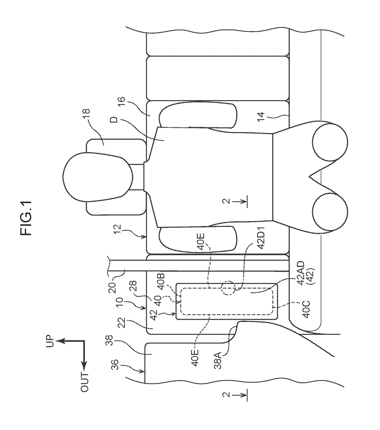
[0014]A front view in which a rear seat 12, to which is applied a rear seat side airbag device 10 relating to the present embodiment, is seen from the vehicle front side, is shown in FIG. 1. Further, FIG. 1 illustrates a state in which a crash test dummy (mannequin), which serves as a model of a passenger who is to be protected, is seated on a seat cushion 14 of the rear seat 12. The dummy is, for example, an AF05 (5th percentile U.S. adult female) World SID (internationally standardized side crash dummy: World Side Impact Dummy). This dummy is seated in a standard seated posture that is prescribed by crash test methods, and the rear seat 12 is positioned at a standard set position that corresponds to this seated posture. Hereinafter, in order to make the explanation easy to understand, the dummy is called “passenger D”.

[0015]As shown in FIG. 1, the rear seat 12 is structured so as to include the seat cushion 14 and a seatback 16. A headrest 18 for supporting the head portion of the...

second embodiment

[0044]A rear seat side airbag device 60 relating to a second embodiment of the present disclosure is described next by using FIG. 5. Note that structural portions that are the same as those of the above-described first embodiment are denoted by the same numbers, and description thereof is omitted.

[0045]As shown in FIG. 5, the basic structure of the rear seat side airbag device 60 relating to the second embodiment is similar to that of the first embodiment, and has a feature in the point that a case 62 is formed in a stepped shape.

[0046]Namely, the case 62 that accommodates the airbag module main body 24 is formed in the shape of a box having an opening portion 62A that opens toward the vehicle front side. A bottom wall 62D of this case 62 is structured so as to support the airbag 44 from the vehicle rear side. Note that the inflator 46 is disposed at the vehicle transverse direction substantially central portion of the bottom wall 62D. Further, a side wall 62E and a side wall 62F ex...

third embodiment

[0050]A rear seat side airbag device 70 relating to a third embodiment of the present disclosure is described next by using FIG. 6. Note that structural portions that are the same as those of the above-described first embodiment are denoted by the same numbers, and description thereof is omitted.

[0051]As shown in FIG. 6, the basic structure of the rear seat side airbag device 70 relating to the third embodiment is similar to that of the first embodiment, and has a feature in the point that a case 72 is formed in a shape that is symmetrical to the left and the right.

[0052]Namely, the case 72 that accommodates the airbag module main body 24 is formed in the shape of a box having an opening portion 72A that opens toward the vehicle front side. A bottom wall 72D of this case 72 is structured so as to support the airbag 44 from the vehicle rear side. Note that the inflator 46 is disposed at the vehicle transverse direction substantially central portion of the bottom wall 72D. Further, a ...


PUM


Abstract

A rear seat side airbag device includes: a case that is provided at a vehicle rear side of a cabin-side wall portion, a plate thickness direction of which is a substantially vehicle longitudinal direction, of a seat side garnish disposed between a vehicle side portion and a seatback of a rear seat, that has an opening portion that opens toward the cabin-side wall portion, and that houses an airbag module main body; an airbag door that covers the opening portion, and that is surrounded by a tear portion and a hinge portion that are formed at regions corresponding to the opening portion; and a spacer that is provided at the airbag door and projects out into the case.

Description

CROSS-REFERENCE TO RELATED APPLICATION[0001]This application is based on and claims priority under 35 USC 119 from Japanese Patent Application No. 2017-173229 filed on Sep. 8, 2017, which is incorporated by reference herein.BACKGROUNDTechnical Field[0002]The present disclosure relates to a rear seat side airbag device.Related Art[0003]Japanese Patent Application Laid-Open (JP-A) No. 2006-088850 discloses a side airbag device. This side airbag device is accommodated within a case that is provided at a seat side garnish (hereinafter called “side garnish”) that is provided between the seatback of a rear seat and a vehicle side portion. The airbag door, which is surround by a tear portion and a hinge portion, is formed the cabin-side wall portion of the side garnish. Further, at the time of a vehicle collision, the airbag that inflates opens the airbag door while rupturing the tear portion from the interior of the case, and, due thereto, the airbag is inflated and expanded between the v...

Claims


Application Information

Patent Timeline
Patent Type & Authority Applications(United States)
IPC IPC(8): B60R21/207B60R21/26B60R21/2165
CPCB60R21/207B60R21/26B60R21/2165B60R2021/2078B60R2021/21537B60R2021/0032B60R21/20B60R21/215
Inventor HIODA, SEIJI
Owner TOYOTA JIDOSHA KK
Why Eureka
Try Eureka