Parallel-connected condenser and cooling device using the same

Inactive Publication Date: 2019-03-14
MAN ZAI IND
View PDF9 Cites 7 Cited by
  • Summary
  • Abstract
  • Description
  • Claims
  • Application Information

AI Technical Summary

Benefits of technology

[0005]An objective of the present invention is to provide a parallel-connected condenser and a cooling device using the same to provide en

Problems solved by technology

As the conventional cooling device only has one condenser, the flow rate of the gaseous coolant may be limited.
Therefore, when the coolant inside the evaporator is heated and

Method used


Image

  • Parallel-connected condenser and cooling device using the same
  • Parallel-connected condenser and cooling device using the same
  • Parallel-connected condenser and cooling device using the same

Examples


Embodiment Construction

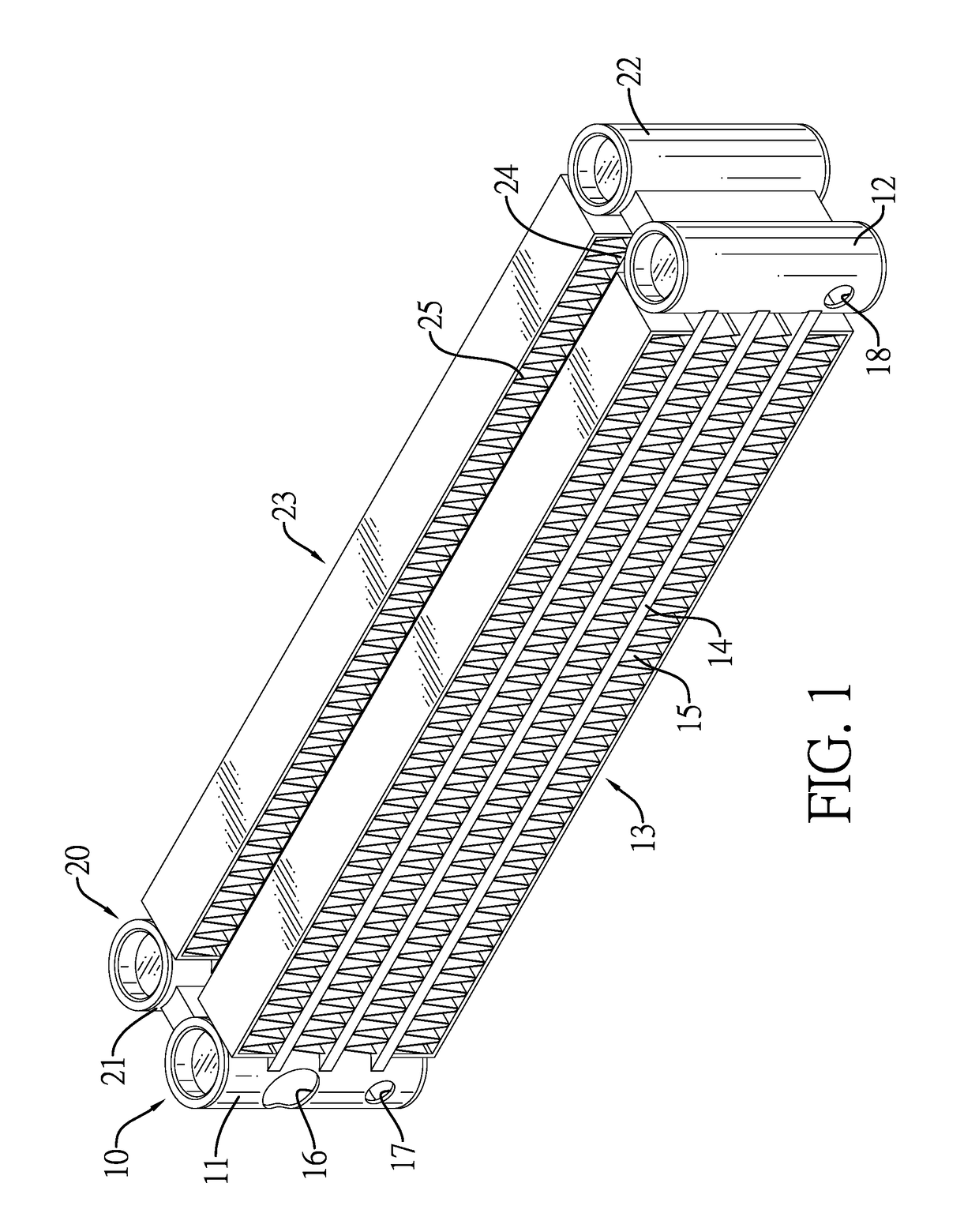
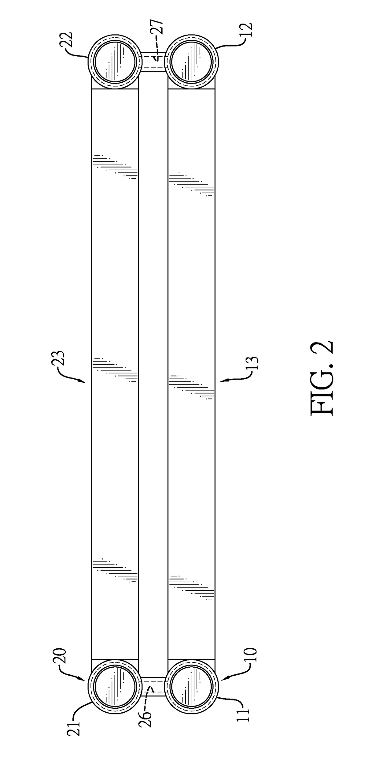
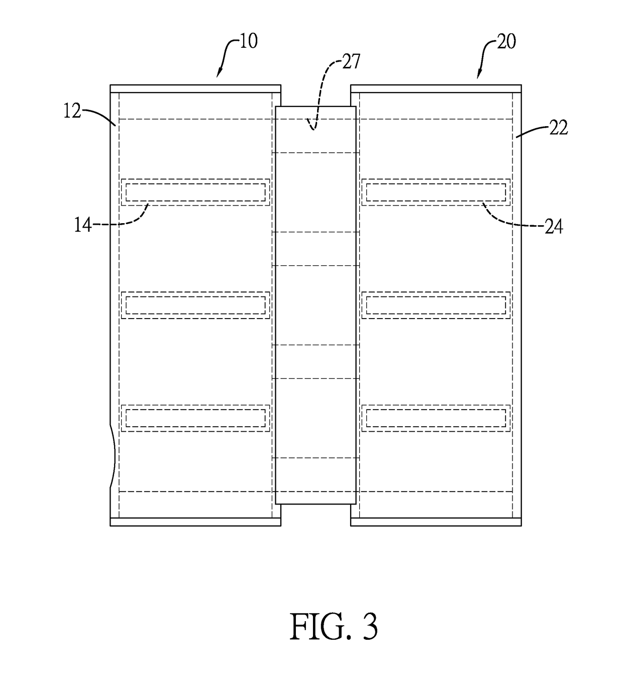
[0034]With reference to FIGS. 1 to 3, a parallel-connected condenser in accordance with the present invention includes a primary condenser assembly 10 and an auxiliary condenser assembly 20.

[0035]The primary condenser assembly 10 has a first primary condenser tube 11, a second primary condenser tube 12 and a primary heat-dissipating mechanism 13. The first primary condenser tube 11 and the second primary condenser tube 12 are vertically mounted and are spaced apart from each other. The primary heat-dissipating mechanism 13 is horizontally mounted between the first primary condenser tube 11 and the second primary condenser tube 12. The primary heat-dissipating mechanism 13 includes multiple primary cooling flat ducts 14 and multiple primary heat sinks 15. The multiple primary cooling flat ducts 14 are horizontally connected between the first primary condenser tube 11 and the primary second condenser tube 12 and are spaced apart from one another. Adjacent two of the multiple primary h...


PUM


Abstract

A cooling device includes a parallel-connected condenser and an evaporator assembly. The parallel-connected condenser has a primary condenser assembly and at least one auxiliary condenser assembly. The evaporator assembly includes an evaporator, a coolant input pipe and a coolant output pipe. Two ends of the coolant input pipe are respectively connected to the evaporator and a first primary condenser tube. Two ends of the coolant output pipe are respectively connected to the evaporator and a second primary condenser tube for the parallel-connected condenser and the evaporator assembly to form a closed coolant circulation loop with coolant filled therein. By virtue of the primary condenser assembly and the auxiliary condenser assembly parallelly connected, gaseous coolant can be circulated through different paths and liquefied to effectively enhance cooling and liquefaction efficiency of coolant when the coolant is circulated through the cooling device.

Description

BACKGROUND OF THE INVENTION1. Field of the Invention[0001]The present invention relates to a parallel-connected condenser and a cooling device using the same and, more particularly, to a parallel-connected condenser with enhanced cooling performance and a cooling device using the same.2. Description of the Related Art[0002]As we know, heat is generated by electronic devices when the electronic devices are operating. To lower the chance of irregular operation or damage to an electronic device arising from an overheat condition, by and large a cooling device is installed at a heat-generating source of the electronic device to absorb heat generated by the heat-generating source to achieve a cooling purpose.[0003]Conventionally, such cooling device includes an evaporator, a condenser and multiple coolant pipes connected with the evaporator and the condenser to form a closed circulation loop with coolant filled inside the circulation loop. Thus, the coolant in the evaporator absorbs heat...

Claims


Application Information

Patent Timeline
IPC IPC(8): F28F9/02F28D15/02
CPCF28F9/027F28D15/0266F28F9/0243F28F2009/0297F28D2021/0031F28F9/262F28D1/0435F28D1/05383F28D15/0275H01L23/3672H01L23/427H01L23/467
Inventor WAN, CHENG-CHIENWAN, CHENG-FENGLIN, HAO-HUILIU, TUNG-HSINHSIAO, WEI-CHECHEN, HSIAO-CHINGLIN, DHAO-JUNG
Owner MAN ZAI IND
Why Eureka
Try Eureka