Medical retractor

a retractor and medical technology, applied in the field of medical retractors, can solve the problems of large burden on the user's hand, inability to manufacture large-sized metal-made retractors, and the possibility of patient suffering from heat shock, so as to ensure reduce the weight of the retractor, and improve the effect of the visibility of the operation field

Active Publication Date: 2019-03-21
SHIMIZU YUSUKE +1
View PDF7 Cites 29 Cited by
  • Summary
  • Abstract
  • Description
  • Claims
  • Application Information

AI Technical Summary

Benefits of technology

[0039]According to one embodiment of the present invention, there is provided the medical retractor capable of ensuring visibility of a field of operation and in the periphery of the field of operation while realizing the reduction in weight of the retractor compared to a conventional steel-made retractor. That is, according to the medical retractor of the present invention, an affected part which opposedly faces the back surface side of the resin functional portion is viewable through the hook-shaped portion. Accordingly, an affected part which is disposed in a shadow of the refractor and is not viewable if the medical retractor is formed of a steel-made retractor is viewable and hence, visibility of a field of operation can be largely increased compared to a conventional steel-made retractor. Also with respect to the trunk portion, an affected part which opposedly faces the back surface side is viewable and hence, even when a first retractor which retracts a tissue on a superficial layer side and a second retractor which retracts a tissue on a deep layer side are used simultaneously, it is possible to view the tissue which is retracted by the first retractor and is positioned on a back side of the second retractor through the trunk portion of the second retractor. Accordingly, visibility of a field of operation can be enhanced compared to the conventional medical retractor.
[0040]According to one embodiment of the invention, not to mention that light which is incident on the proximal end of the trunk portion from the light source of the grip portion is emitted from the distal ends and corner portions of the hook-shaped portion and the like and is irradiated to an affected part in the periphery of the medical retractor, leaked light is generated from a wall surface parallel to an advancing direction of light and hence, it is possible to largely increase visibility of an affected part which opposedly faces such a wall surface (back surface) when viewed from a wall surface (front surface) side on a side opposite to the affected part. Accordingly, the visibility of a field of operation can be enhanced compared to the prior art.
[0041]According to one embodiment of the invention, with such a medical retractor, it is possible to prevent a possibility that a liquid (body fluid, drug solution or the like) which has a possibility of being adhered to a connecting portion between the grip portion and the resin functional portion during an operation intrudes into the inside of the grip portion through a gap in the connecting portion. Accordingly, it is possible to eliminate lowering of light emitting intensity of the light source and short-circuiting of an inner electric system.
[0042]According to one embodiment of the invention, with such a medical retractor, light which is incident on the resin functional portion from the light source minimally leaks to the outside due to an effect of closing light in the layer boundary and hence, a quantity of light which reaches the hook-shaped portion extending from the distal end of the trunk portion can be increased. Further, by selecting a direction approximately orthogonal to the back surface of the resin functional portion as the direction of the layer boundary, it is possible to ensure leaked light to the back surface side at the same level or above corresponding to leaked light when a resin functional portion does not have the layered structure and hence, it is possible to prevent lowering of an effect of enhancing back-surface-side visibility by leaked light.
[0043]According to one embodiment of the invention, with such a medical retractor, the back surface and the front surface of the resin functional portion are respectively formed flat and hence, it is possible to ensure favorable visibility of an affected part which opposedly faces the back surface as viewed from a front surface side. Further, it is possible to view the affected part in an actual size.
[0044]According to one embodiment of the invention, with such a medical retractor, an affected part which opposedly faces the back surface is viewed in an enlarged state from a front surface side and hence, while ensuring visibility of the affected part which opposedly faces the back surface of the resin functional portion from the front surface side, it is also possible to view a fine part of a tissue of the affected part.

Problems solved by technology

A metal-made retractor is heavy and hence, a large burden is placed on a user's hand.
A metal-made retractor is heavy and hence, a large-sized metal-made retractor cannot be manufactured.
Since a metal-made retractor has high thermal conductivity, the metal-made retractor rapidly absorbs heat from a tissue of an affected part thus giving rise to a possibility that the patient suffers from a heat shock.
Since metal-made retractors are expensive, the inventory of retractors at facilities in a hospital is liable to be constantly insufficient.
Further, as drawbacks in medical field, patent document 2 points out drawbacks brought about by a shortage of illumination, a shortage of reflection or the like in a field of operation.

Method used


Image

  • Medical retractor
  • Medical retractor
  • Medical retractor

Examples


first embodiment

(1) First Embodiment

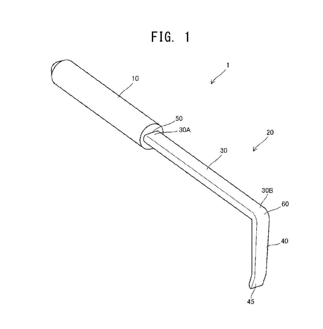
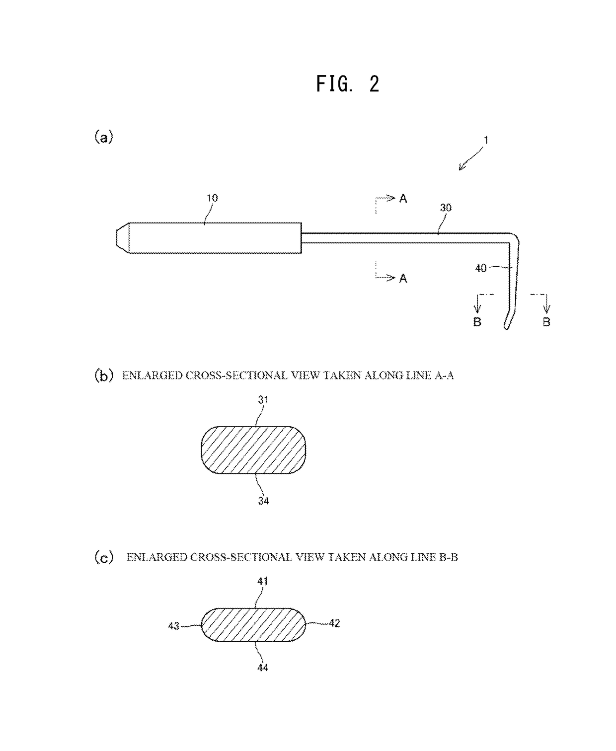
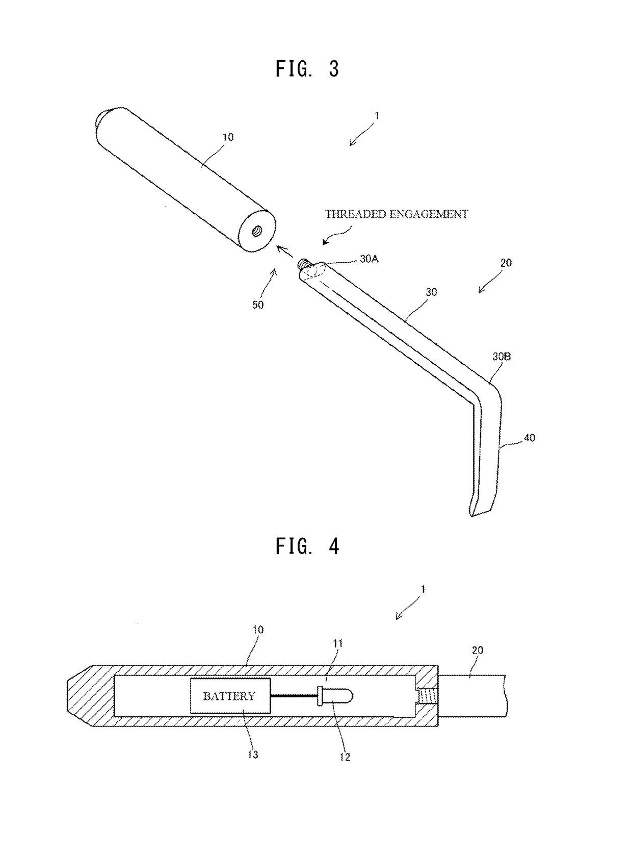
[0083]FIG. 1 to FIG. 4 are views for describing a medical retractor 1 according to this embodiment. FIG. 1 is a perspective view showing the medical retractor 1, FIG. 2(a) to (c) are a side view and cross-sectional views of the medical retractor 1, FIG. 3 is a perspective view showing a disassembled state of a connecting portion of the medical retractor 1, and FIG. 4 is a cross-sectional view of a grip portion of the medical retractor 1.

[0084]In this specification, a tissue of an operation target and a part which a doctor considers it necessary to visually observe during an operation in association with the operation are referred to as “affected part”, and a region including the affected part and the periphery of the affected part is referred to as “field of operation”.

[0085]The medical retractor 1 includes: a grip portion 10 which a practitioner such as a doctor or an assistant holds; and a resin functional portion 20 which is used in a state where the resin fun...

second embodiment

(2) Second Embodiment

[0107]FIG. 5 is a view for describing a shape of a medical retractor 200 according to a second embodiment. The medical retractor 200 shown in FIG. 5 has substantially the same configuration as the medical retractor 1 according to the above-mentioned first embodiment except for shapes of a front surface and a back surface of a trunk portion 30 of a resin functional portion 20 and shapes of a front surface and a back surface of a hook-shaped portion 40 of the resin functional portion 20. Accordingly, the constitutional elements other than the back surface and the front surface of the resin functional portion 20 are given the same symbols as the corresponding constitutional elements of the first embodiment, and their detailed description is omitted.

[0108]The trunk portion 30 is formed into an approximately elliptical shape in cross section substantially perpendicular to the longitudinal direction of the trunk portion 30. Accordingly, front surfaces 231, 241 and bac...

third embodiment

(3) Third Embodiment

[0113]FIG. 6 is a view for describing a shape of a medical retractor 300 according to a third embodiment. The medical retractor 300 shown in FIG. 6 has substantially the same configuration as the medical retractor 1 according to the above-mentioned first embodiment except for a point that a ridge is formed on front surfaces 31, 41 of a resin functional portion 20. Accordingly, the constitutional elements other than the ridge are given the same symbols as the corresponding constitutional elements of the first embodiment, and their detailed description is omitted.

[0114]In the medical retractor 300, a ridge 370 is formed on the front surfaces 31, 41 of the resin functional portion 20 in an extending manner along the longitudinal direction of the resin functional portion 20 at substantially center of the front surfaces 31, 41. By forming the ridge 370 on the resin functional portion 20, the resin functional portion 20 is reinforced so that rigidity of the resin funct...


PUM


Abstract

A medical retractor is capable of ensuring visibility in a field of operation and in the periphery of the field of operation while realizing the reduction of weight of the retractor compared to a conventional steel-made retractor. A medical retractor includes: a grip portion; and a resin functional portion made of a transparent resin and extending from the grip portion. The resin functional portion has: a trunk portion which has a proximal end thereof connected to the grip portion; and a hook-shaped portion extending in a hook shape from a distal end of the trunk portion. The resin functional portion is configured to allow the viewing of an affected part which opposedly faces a back surface of the resin functional portion from a front surface side in a see-through manner.

Description

CROSS REFERENCE TO RELATED APPLICATION[0001]This is a Continuation of U.S. application Ser. No. 15 / 327,215 filed on Jan. 18, 2017, which was a U.S. National Phase application under 35 U.S.C. 371 of International Application PCT / JP2015 / 068331 filed on Jun. 25, 2015, which, in turn, claimed the priority of Japanese Patent Application No. 2014-187131 filed on Sep. 13, 2014, the entire content of those applications are incorporated herein by reference.TECHNICAL FIELD[0002]The present invention relates to a medical retractor.BACKGROUND ART[0003]Currently, various steel-made utensils are used in medical field. “steel-made utensil” means an instrument for operations made of metal such as stainless steel. Steel-made utensils include tweezers, needle holders, scalpels, scissors, forceps, wound retractors, chisels, cupped forceps and the like. Kinds of such steel-made utensils amount to approximately 30, and there are several hundred variations in shapes of distal ends and sizes of these stee...

Claims


Application Information

Patent Timeline
Patent Type & Authority Applications(United States)
IPC IPC(8): A61B17/02A61B1/06A61B1/32A61B90/30A61B17/00
CPCA61B2090/308A61B2090/306A61B2090/304A61B90/30A61B2017/00734A61B2017/00473A61B2017/00907A61B1/32A61B1/06A61B17/02A61B2017/0046
Inventor SHIMIZU, YUSUKEMATSUTA, SATOSHIARADONO, GO
Owner SHIMIZU YUSUKE
Why Eureka
Try Eureka