
Method and apparatus for producing hollow articles made of injection moulded plastic material

a technology of injection moulding and hollow objects, which is applied in the direction of coatings, etc., can solve the problems of moulded components that are susceptible to displacement or flexural deflection, aesthetic defects, and possible breakage of the cor

Active Publication Date: 2019-03-21
INGLASS SPA
View PDF0 Cites 2 Cited by
  • Summary
  • Abstract
  • Description
  • Claims
  • Application Information

AI Technical Summary

Benefits of technology

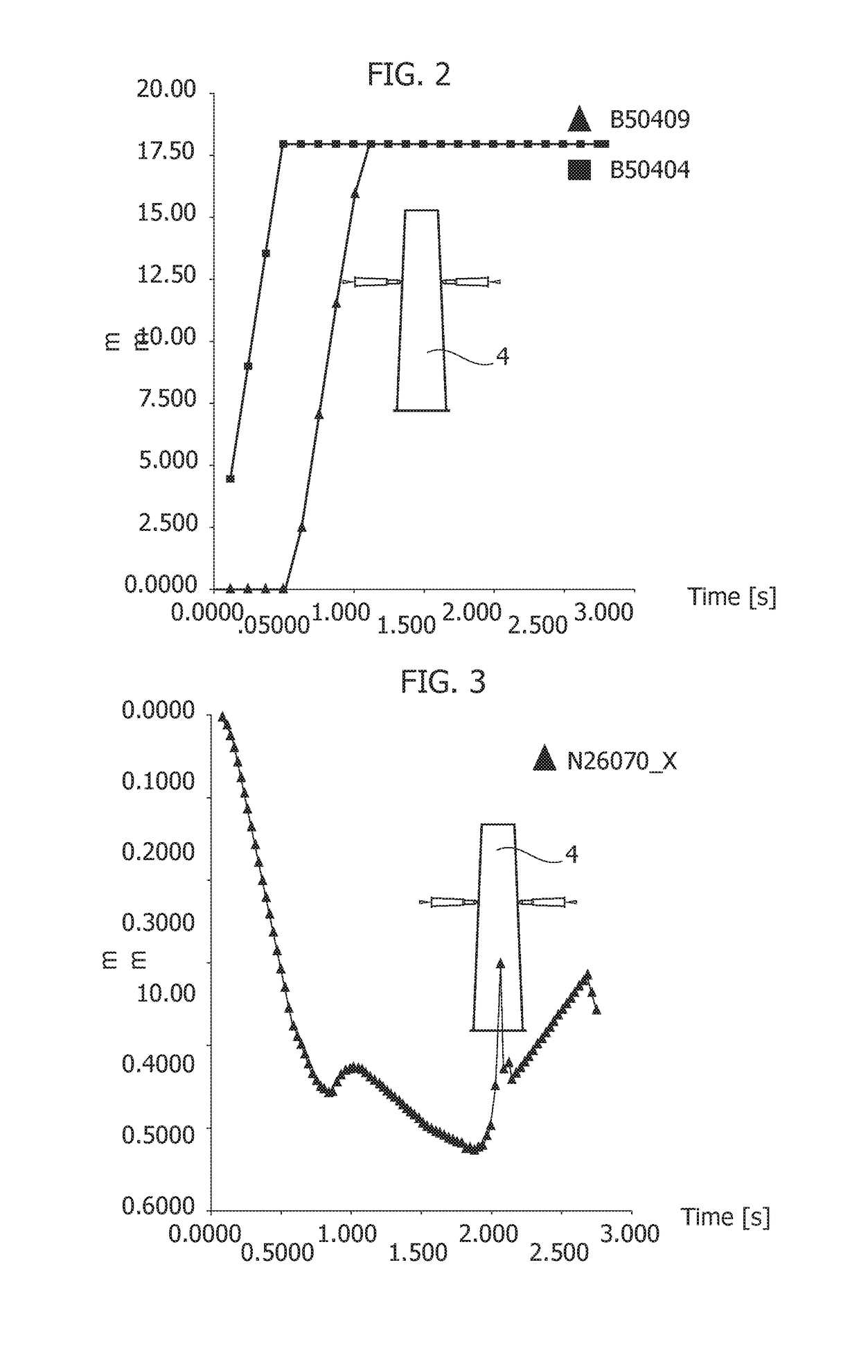
The present invention is about a new method for injection molding hollow articles that eliminates bending and structural defects, and meets design requirements. This is achieved by detecting and controlling a flexural deflection of the core during injection, and adjusting among others the position, speed, acceleration, and stroke of the pin valve to reduce or eliminate the deflection. The invention also includes an apparatus for implementing this method.

Problems solved by technology

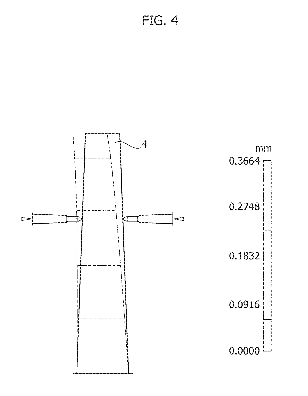
In the injection moulding of hollow articles, particularly of the elongated shape and with thin wall, there arises the problem related to the fact that during the step of filling the space comprised between the mould and the core, the latter can be subjected to displacements or flexural deflections a due to unavoidable unbalancing of the injected plastic material and acting in an unbalanced manner on one side and on the opposite side of the core.
The displacement or deflection of the core causes several drawbacks such as for example the possible breaking of the core, aesthetic defects of the moulded components, and above all structural defects of such components due to failure to meet the relative design nominal thicknesses requirements.
However, this has the sole purpose of avoiding damage during the injection and post-injection step, e.g. due to the fact that the component cannot be extracted, and the core deflection cannot be controlled.

Method used


Image

  • Method and apparatus for producing hollow articles made of injection moulded plastic material
  • Method and apparatus for producing hollow articles made of injection moulded plastic material
  • Method and apparatus for producing hollow articles made of injection moulded plastic material

Examples


Embodiment Construction

[0019]The following description refers to production by means of injection moulding of hollow articles made of plastic material such as the one schematically represented in FIG. 12 and indicated with C: it is a container with elongated shape (for example length equivalent to 350 mm) and a thin wall (nominal thickness for example equivalent to 2 mm).

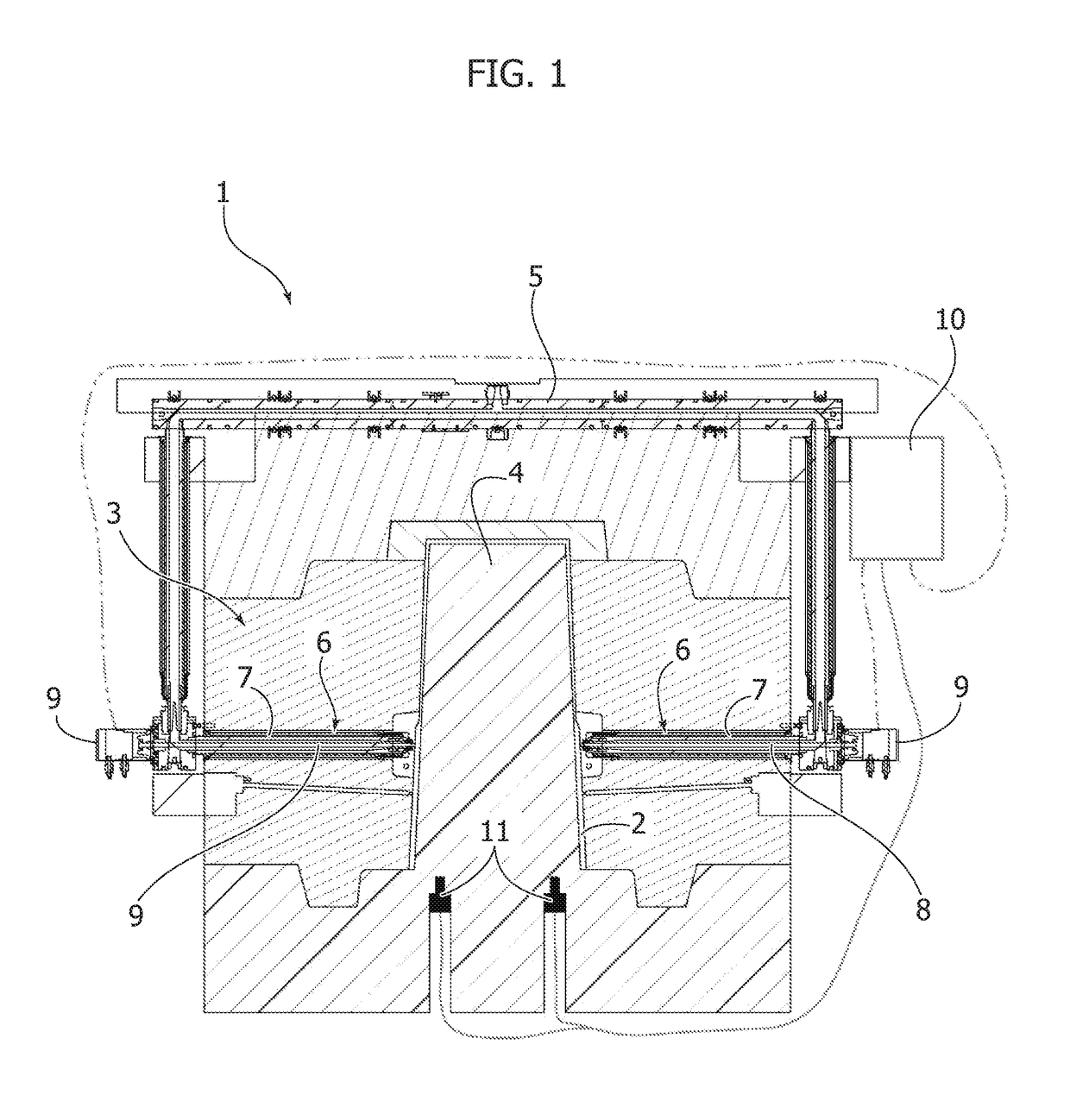
[0020]The recipient C is produced using an apparatus schematically represented in FIG. 1, comprising a mould 1 having a cavity 2, a die 3, a core 4 couplable with the die (3) to delimit a space corresponding to the shape of the recipient C and a system for injecting the plastic material into such space.

[0021]The injection system typically comprises a hot runner or hot chamber 5 supplied by a press and connected, in the case of the illustrated example, to a pair of injectors 6 arranged on opposite sides with respect to the cavity 2 of the mould 1. It should be observed that the number and arrangement of the injectors could be different fro...


PUM

PropertyMeasurementUnit
thicknessaaaaaaaaaa
lengthaaaaaaaaaa
displacementaaaaaaaaaa

Abstract

A method and apparatus for producing hollow articles made of injection moulded plastic material by a mould having a die within which there is inserted a core, and at least one injector including a pin valve displaceable between a closing position and an opening position for injecting the pressurized plastic material into a space comprised between the die and the core. During the injection, any flexural deflection of the core is detected and the pin valve of the or of each injector is displaced in a controlled fashion to adjust a pressure and a flow rate of the injected plastic material, so as to reduce or eliminate such deflection of the core.

Description

FIELD OF THE INVENTION[0001]The present invention generally regards the injection moulding of plastic materials, and in particular it regards a method and an apparatus for the production of hollow articles made of injection moulded plastic material.STATE OF THE ART[0002]The injection moulding of hollow articles made of plastic material is typically carried out by means of a mould having a die defining a cavity into which a core is inserted. At least one injector including a pin valve displaceable between a closing position and an opening position injects the pressurised plastic material into the space comprised between the mould and the core. The displacement of the pin valve of the injector is carried out by a fluid or electrical actuator, in the second case for example by a rotary motor as described and illustrated in document U.S. Pat. No. 9,102,085 on behalf of the Applicant.[0003]In the injection moulding of hollow articles, particularly of the elongated shape and with thin wal...

Claims


Application Information

Patent Timeline
Patent Type & Authority Applications(United States)
IPC IPC(8): B29C45/14B29C45/23B29C45/77B29C45/76
CPCB29C45/14836B29C45/231B29C45/77B29C45/768B29C2945/76103B29C2945/7626B29C2945/76381B29C2945/76454B29C2945/76545B29C2945/76658B29C2945/76859B29C45/2602B29C45/2806B29C45/76B29C45/80B29C2045/2872B29C2945/76006B29C2945/76083B29C2945/76254B29C2945/76287B29C2945/76498
Inventor BAZZO, MAURIZIOROSSI, MASSIMO
Owner INGLASS SPA
Learn More