Combustion device

a combustion device and combustion technology, applied in the direction of combustion treatment, combustion process, combustion regulation, etc., can solve the problems of abrupt and unpleasant clattering noise, reverse flow may penetrate into the interior of the facility, etc., and achieve the effect of avoiding the danger of collision noise high

Active Publication Date: 2019-03-28
NORITZ CORP
View PDF12 Cites 2 Cited by
  • Summary
  • Abstract
  • Description
  • Claims
  • Application Information

AI Technical Summary

Benefits of technology

[0017]According to the constitution described above, since during combustion operation of another combustion device the internal pressure within the common exhaust duct is high because combustion exhaust is flowing in it, accordingly the valve element of the check valve will not rise abruptly even if air purge is started from the not-yet-burning state, so that there is no danger of the collision noise becoming high.

Problems solved by technology

However, if only some of the combustion devices among the plurality of combustion devices are being operated to perform combustion, then, since the blower fans of the combustion devices that are in the non-combusting state are not being rotated, accordingly the combustion exhaust may flow in reverse from the common exhaust duct into the exhaust ports of one or more of the combustion devices that are in the non-combusting state, and there is a fear that this reverse flow may penetrate into the interior of the facility.
When a check valve as shown in FIG. 2 is employed, during air purge (i.e. pre-purging) when the combustion device is ignited and when the blower fan is rotationally driven at a high acceleration in order to reach its predetermined rated rotational speed in a short time interval of the order of one second, the valve plate 26 of the above described check valve rises sharply and collides with the stopper 28, so that there is the problem that an abrupt and unpleasant clattering noise is generated.

Method used


Image

  • Combustion device
  • Combustion device
  • Combustion device

Examples


Embodiment Construction

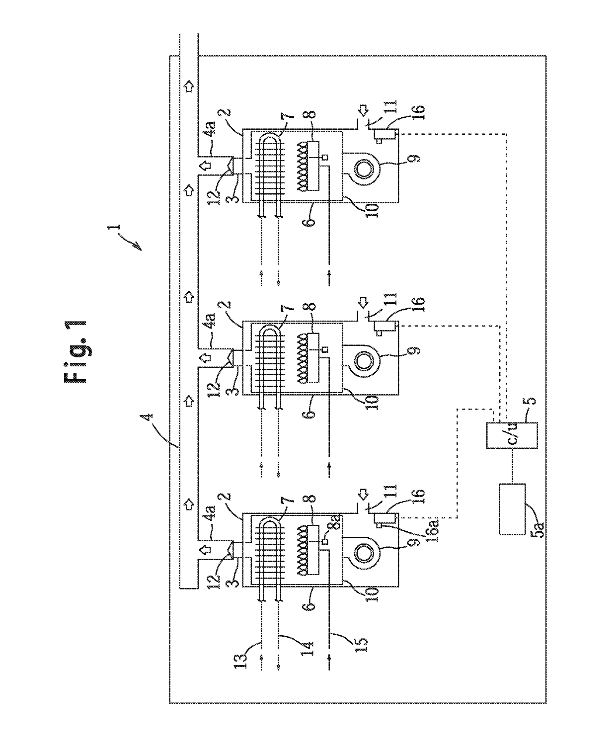
[0023]First, a compound combustion system in which a plurality of combustion devices that are used for supplying hot water are installed will be explained with reference to FIG. 1. This compound combustion system 1 comprises three combustion devices 2 that are arranged in parallel, a common exhaust duct 4 that is connected in parallel to exhaust ports 3 of these three combustion devices 2, and a main control unit 5.

[0024]Each of the combustion devices 2 is a gas-burning type combustion device and has a outer casing 6, and a box shaped inner casing 10 disposed in an upper portion and an intermediate portion of the interior of the outer casing 6, a heat exchanger 7 is disposed in an upper portion of the interior of the inner casing 10, a burner 8 (i.e. a combustion unit) and an igniter 8a (i.e. an ignition means) are disposed in a lower portion of the inner casing 10, and a blower fan 9 is disposed in the interior of the outer casing 6 below the inner casing 10 so that an air blowing ...


PUM


Abstract

The combustion device includes: a burner; an igniter; a fuel supply unit that supplies fuel to the burner; a blower fan that supplies air for combustion; an exhaust port that discharges combustion exhaust; a device control unit that, before ignition of fuel supplied to the burner by operation of the igniter, performs air purge of the burner at a predetermined air blowing amount by driving the blower fan; and a setting means that is set when a check valve for preventing back flow of exhaust is connected to the exhaust port. When the setting means is set to indicate that the check valve is connected, the device control unit controls the operation of the blower fan so that slow-start air purge is performed in which the time interval from the start of air purge until the predetermined air blowing amount is reached becomes longer, than in the case in which no such check valve is connected.

Description

BACKGROUND OF THE INVENTION[0001]The present invention relates to a combustion device, and in particular relates to a combustion device in which a check valve is connected to an exhaust port, in order for the exhaust port to be connected to an exhaust duct that is utilized in common by a plurality of combustion devices.[0002]In the prior art, a compound combustion device is per se known in which a plurality of combustion devices each of which comprises individual combustion unit and individual blower fan are installed in a facility in parallel, and the exhaust ports of these combustion devices are all connected to a common exhaust duct. With such a compound combustion device, operation is performed to discharge the combustion exhaust from each of the combustion devices to the exterior of the facility via the common exhaust duct by rotating the respective blower fan, while adjusting the number of operating combustion devices according to the load.[0003]However, if only some of the co...

Claims


Application Information

Patent Timeline
Patent Type & Authority Applications(United States)
IPC IPC(8): F23N5/24
CPCF23N5/245F23J13/04F23J2211/20F23J2213/70F23L17/00F23N3/08
Inventor MASUMOTO, KENTAROTANAKA, HIROAKIKURIYAMA, TETSUNORIMANDAI, KEIICHIKUSAKABE, MAKOTOSATO, ISAOKINUGASA, TOMOFUMI
Owner NORITZ CORP
Why Eureka
Try Eureka