Plasma processing apparatus
a technology of processing apparatus and plasma, which is applied in the direction of coating, chemical vapor deposition coating, electric discharge tubes, etc., can solve the problems of abnormal discharge in film forming containers
- Summary
- Abstract
- Description
- Claims
- Application Information
AI Technical Summary
Benefits of technology
Problems solved by technology
Method used
Image


Examples
first embodiment
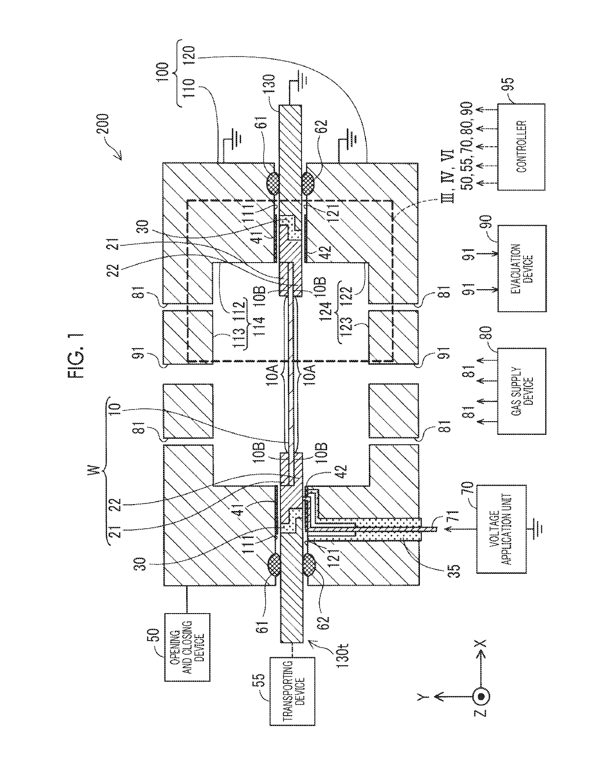
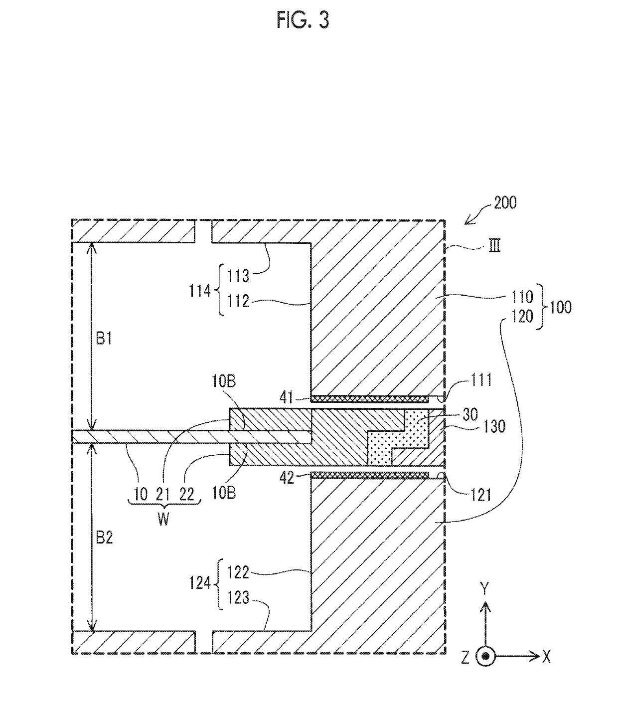
[0022]FIG. 1 is a schematic sectional view illustrating a configuration of a plasma processing apparatus 200 according to a first embodiment. FIG. 2 is an exploded perspective view of the plasma processing apparatus 200. In FIGS. 1 and 2, X, Y, and Z axes substantially orthogonal to each other are shown. Being substantially orthogonal includes a range of 90°±20°. In the first embodiment, the Y direction is a substantially vertical direction, and the X direction is a substantially horizontal direction. The Z direction is a direction perpendicular to the substantially vertical direction and the substantially horizontal direction. This is also applied to the following figures.
[0023]The plasma processing apparatus 200 is an apparatus which performs plasma processing on a portion of a conductive workpiece W having a flat plate shape. The plasma processing is a process of performing film formation or etching on the workpiece W using a plasma. In the first embodiment, the workpiece W inclu...
second embodiment
[0055]FIG. 6 is an enlarged partial sectional view of a plasma processing apparatus 200a in a second embodiment. FIG. 6 illustrates a portion of the plasma processing apparatus 200a corresponding to VI illustrated in FIG. 1. The plasma processing apparatus 200a of the second embodiment is different from the plasma processing apparatus 200 of the first embodiment in that an insulating layer 41a covers the surface of the side portion 112 in addition to the portion of the first peripheral edge portion 111 facing the workpiece W. An insulating layer 42a covers the surface of the side portion 122 in addition to the portion of the second peripheral edge portion 121 facing the workpiece W. The insulating layer 41a is formed by coating the first peripheral edge portion 111 and the side portion 112 with an insulating material, and the insulating layer 42a is formed by coating the second peripheral edge portion 121 and the side portion 122 with an insulating material. The other configurations...
third embodiment
[0059]Hereinafter, in third to fifth embodiments, other configurations of the plasma processing apparatus will be described. FIG. 7 is a view illustrating a plasma processing apparatus 200m in the third embodiment. Also in the third embodiment, as in the first embodiment, portions of a first peripheral edge portion 111m and a second peripheral edge portion 121m facing the workpiece W are covered with the insulating layers 41, 42. The plasma processing apparatus 200m of the third embodiment is different from the plasma processing apparatus 200 of the first embodiment in that the shortest distance from the connection portion Q1 between a first recessed portion 114m of a first mold 110m and the first peripheral edge portion 111m and the connection portion Q2 between a second recessed portion 124m of a second mold 120m and the second peripheral edge portion 121m to the contact points P1, P2 between the workpiece W and the insulating member 30 along the first peripheral edge portion 111m...
PUM
| Property | Measurement | Unit |
|---|---|---|
| thickness | aaaaa | aaaaa |
| thickness | aaaaa | aaaaa |
| thickness | aaaaa | aaaaa |
Abstract
Description
Claims
Application Information
 - R&D Engineer
- R&D Manager
- IP Professional
- Industry Leading Data Capabilities
- Powerful AI technology
- Patent DNA Extraction
Browse by: Latest US Patents, China's latest patents, Technical Efficacy Thesaurus, Application Domain, Technology Topic.
© 2024 PatSnap. All rights reserved.Legal|Privacy policy|Modern Slavery Act Transparency Statement|Sitemap