
Multi-gap pseudospark electron beam source capable of suppressing flashover

An electron beam source and multi-gap technology, applied in the direction of solid cathode components, etc., can solve the problems of damage to the discharge chamber, breakdown of the isolation insulating sheet, and limitation of the performance of the electron beam, so as to achieve the improvement of the breakdown voltage of the beam source and the suppression of abnormal discharge , the effect of compact structure

Active Publication Date: 2018-05-22
SHANGHAI JIAO TONG UNIV
View PDF0 Cites 3 Cited by
  • Summary
  • Abstract
  • Description
  • Claims
  • Application Information

AI Technical Summary

Problems solved by technology

However, under high voltage, the distorted electric field at the edge of the metal pole piece, the arc flash along the surface of the isolation insulating sheet, etc. will easily lead to abnormal breakdown, and the electron beam cannot be generated.
[0005] Abnormal discharge phenomena such as arc along the surface seriously affect the stability and reliability of the pseudo-spark electron beam source, limit the further improvement of the electron beam performance, and also reduce the service life of the pseudo-spark electron beam source, and even cause the discharge cavity damage to

Method used


Image

  • Multi-gap pseudospark electron beam source capable of suppressing flashover
  • Multi-gap pseudospark electron beam source capable of suppressing flashover
  • Multi-gap pseudospark electron beam source capable of suppressing flashover

Examples


Embodiment 1

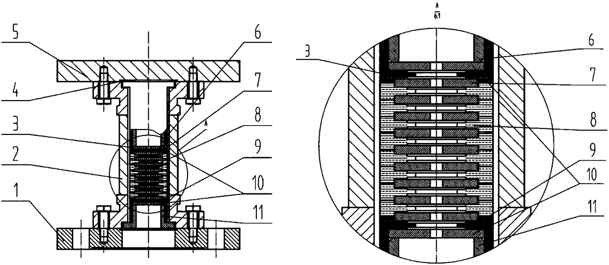
[0025] Such as figure 2 As shown, this embodiment includes: sequentially screwing the blind flange 5, the ceramic spacer 2 and the through-hole flange 1 to form an external support; the hollow electrodes 6, 11 and their insulating sleeves 3, 9 symmetrically placed at both ends of the ceramic spacer 2 , the intermediate electrodes 7 and intermediate insulating sheets 8 arranged alternately in the ceramic spacer 2 form a discharge cavity. The discharge chamber is axially positioned in the external support by the metal seal ring 4 .

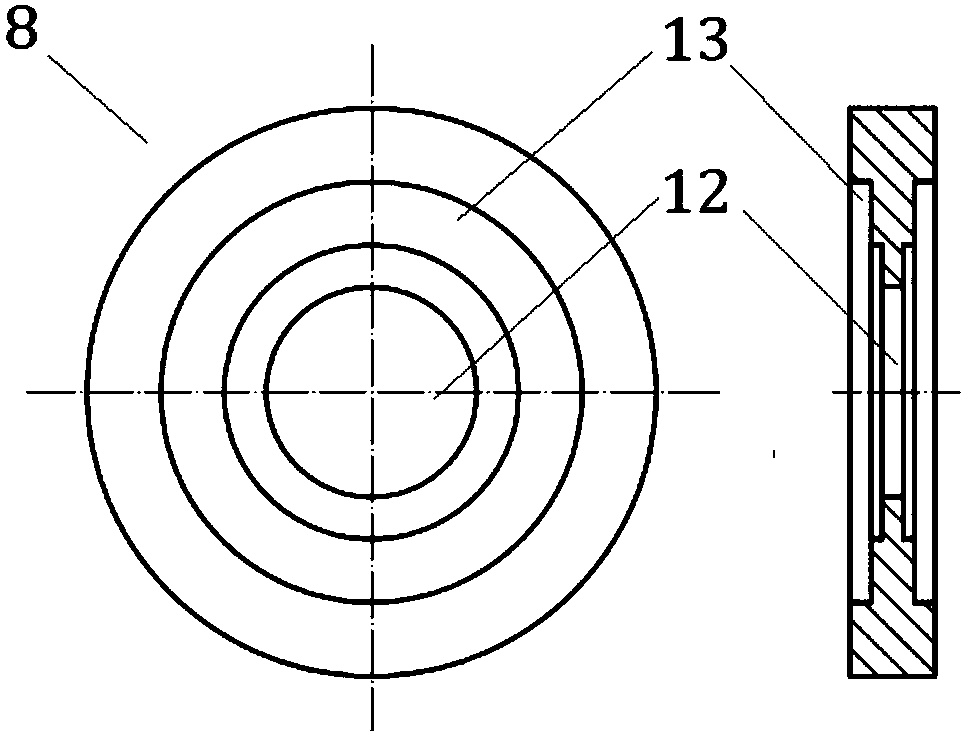
[0026] Such as Figure 4 The shown cathode insulating sleeve 3 surrounds the hollow cathode 6, and as figure 2 The way shown is installed in the ceramic sleeve 2 . The central through hole 12 at the bottom of the cathode insulating sleeve 3 provides a discharge gap. Such as Figure 4 The cathode insulating sleeve 3 shown has a counterbore 13 coaxial with the middle through hole 12, and the depth of the counterbore is half the thickness of the...


PUM


Abstract

The invention discloses a multi-gap pseudospark electron beam source capable of suppressing flashover. The multi-gap pseudospark electron beam source capable of suppressing flashover comprises a blindflange, a ceramic isolation sleeve and a through hole flange which are connected in sequence, hollow electrodes which are symmetrically placed at two ends inside the ceramic isolation sleeve and insulation sleeves thereof, and middle electrode and middle insulation plates which are alternatively superposed in the ceramic isolation sleeve. the hollow electrodes located at the two ends, the insulation sleeves thereof and the middle electrodes located in the middle for electron beam focusing and acceleration form a discharging cavity. A multi-gap pseudospark electron beam source capable of suppressing flashover can be acquired and a high-energy electron beam can be obtained. The multi-gap pseudospark electron beam source effectively suppresses abnormal discharge in a pseudospark discharge process through protecting the edge of a metal pole plate and cutting and hindering formation of flashover along the surface, the energy of the electron beam is improved, and the discharge stability andthe reliability are improved.

Description

technical field [0001] The invention relates to a technology in the field of pseudo-spark discharge, in particular to a multi-gap pseudo-spark electron beam source capable of suppressing arc flash. Background technique [0002] Pseudo-spark discharge is a gas low-pressure discharge located in the left half of the Paschen curve. The discharge pressure is generally tens to hundreds of millitorr. As the gas pressure decreases, the breakdown voltage will rise rapidly. [0003] There are five phases of pseudospark discharge, starting from the hollow cathode discharge phase where the electron beam is generated. The pulsed electron beam generated by pseudospark discharge has the characteristics of high beam current density, high energy density, high brightness, and self-focusing. Therefore, the pseudospark electron beam has a good application prospect in the surface modification of materials, X-ray generation, thin film preparation, and high-frequency microwave generation. [00...

Claims


Application Information

Patent Timeline
Patent Type & Authority Applications(China)
IPC IPC(8): H01J17/02H01J17/06
Inventor 霍卫杰胡静赵万生
Owner SHANGHAI JIAO TONG UNIV
Learn More