
Electronic device with optical sensor

a technology of optical sensor and electronic device, applied in the field of electronic devices, can solve the problems of difficult to equip refractive lenses in small electronic devices, burdensome security company use for security purposes, and less secure password setting

Active Publication Date: 2019-04-04
SAMSUNG ELECTRONICS CO LTD
View PDF0 Cites 12 Cited by
  • Summary
  • Abstract
  • Description
  • Claims
  • Application Information

AI Technical Summary

Benefits of technology

The patent text discusses different optical structures used for detecting images, such as fingerprints, on small electronic devices. However, these structures have limitations in providing sufficient information for user authentication. The technical effect of the patent is to provide an improved optical structure that can better detect images with as much information as required for user authentication.

Problems solved by technology

However, these ways have their own disadvantages—e.g., password setting is a less secure way due to the likelihood of password leakage, and using a third party security company for security purposes is burdensome.
However, a refractive lens may be difficult to equip in a small electronic device, e.g., a mobile communication terminal.
A pin hole array, a liquid crystal cell array, or a micro-lens array may be easy to place in a small electronic device, but they are not workable enough to give detection of an image containing as much information as required for user authentication.
However, the limited space inside the electronic device would not make it possible.

Method used


Image

  • Electronic device with optical sensor
  • Electronic device with optical sensor
  • Electronic device with optical sensor

Examples


Embodiment Construction

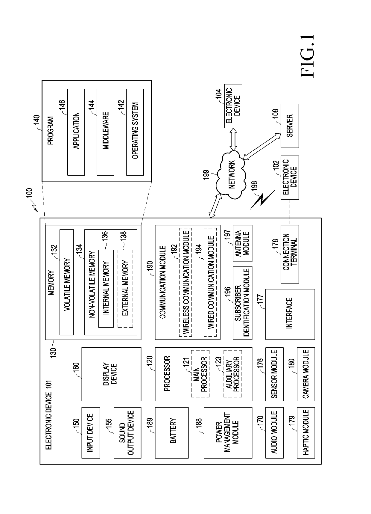
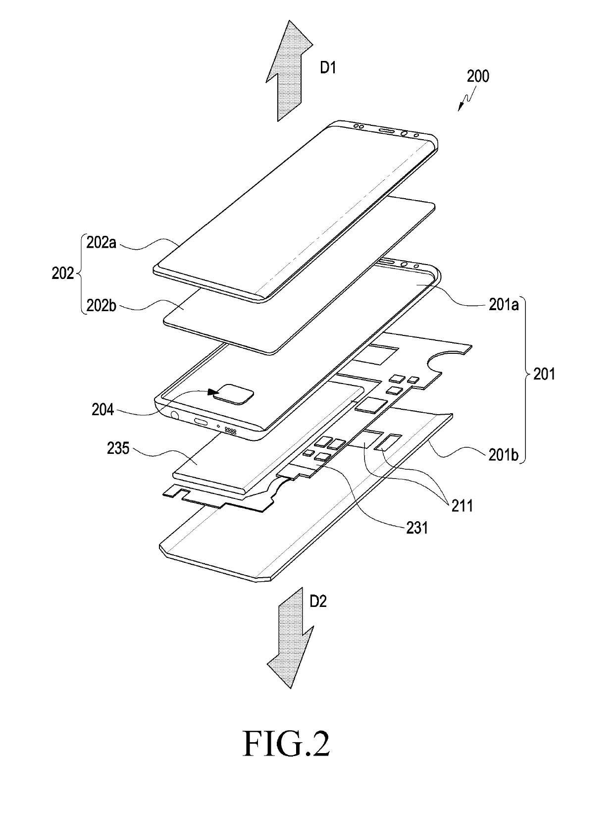
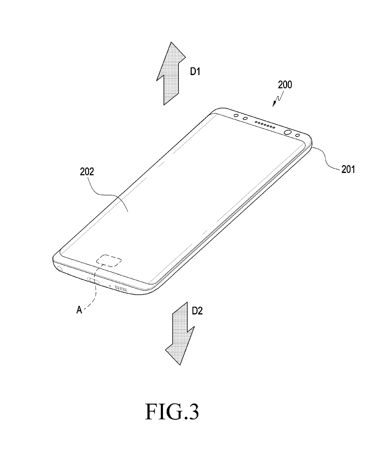
[0029]The following description with reference to the accompanying drawings is provided to assist in a comprehensive understanding of various embodiments of the disclosure as defined by the claims and their equivalents. It includes various specific details to assist in that understanding but these are to be regarded as merely exemplary. Accordingly, those of ordinary skill in the art will recognize that various changes and modifications of the various embodiments described herein can be made without departing from the scope and spirit of the disclosure. In addition, descriptions of well-known functions and constructions may be omitted for clarity and conciseness.

[0030]The terms and words used in the following description and claims are not limited to the bibliographical meanings, but, are merely used by the inventor to enable a clear and consistent understanding of the disclosure. Accordingly, it should be apparent to those skilled in the art that the following description of variou...


PUM

PropertyMeasurementUnit
Areaaaaaaaaaaa
Wavelengthaaaaaaaaaa

Abstract

An electronic device is provided. The electronic device includes an optical sensor, the optical sensor comprising a lighting device configured to emit light, a sensor layer including an array of sensors configured to detect first image information corresponding to an object from light reflected by the object, and a filter layer including openings configured to transmit the light reflected by the object, the filter layer disposed on the sensor layer, wherein the first image information is different from an image of the object identified with naked eyes. The electronic device may be diversified according to embodiments.

Description

CROSS-REFERENCE TO RELATED APPLICATION(S)[0001]This application is based on and claims priority under 35 U.S.C. § 119(a) of a Korean patent application number 10-2017-0127352, filed on Sep. 29, 2017, in the Korean Intellectual Property Office, the disclosure of which is incorporated by reference herein in its entirety.BACKGROUND1. Field[0002]The disclosure relates to electronic devices. More particularly, the disclosure relates to sensors for detecting object images or biometric information about users via an optical structure and electronic devices including the sensors.2. Description of Related Art[0003]Generally, the electronic device means a device performing a particular function according to the electronic device's installed program, such as a home appliance, an electronic scheduler, a portable multimedia player, a mobile communication terminal, a tablet PC, a video / sound device, a desktop PC or laptop computer, a navigation for automobile, etc. For example, electronic devices...

Claims


Application Information

Patent Timeline
IPC IPC(8): G06K9/00G06F3/041G02F1/1333
CPCG06K9/0004G06K9/0012G06F3/0412G02F1/13338G06V40/1318G06V40/1347G02B1/11G02B5/28H10K59/35H10K50/805G06V40/1394
Inventor LEE, JIN-EUISEO, YOUNG-MINLEE, YOUNG-SOOPARK, YONG-CHEOLRHEE, BONG-JAE
Owner SAMSUNG ELECTRONICS CO LTD
Learn More