Surface coated filter method

a filter media and surface coating technology, applied in the field of filters, can solve the problems of easy tearing of attached structures, low puncture inability to provide strong bonding surfaces, so as to improve the puncture and crush resistance of filter media, prevent leakage paths, and improve the effect of puncture resistan

Active Publication Date: 2019-04-11
BALDWIN FILTERS
View PDF1 Cites 6 Cited by
  • Summary
  • Abstract
  • Description
  • Claims
  • Application Information

AI Technical Summary

Benefits of technology

[0050]Certain advantages may flow from various aspects discussed above. One potential advantage is the ability of the polymeric coating to stabilize the dimensions of the filter media pack during storage.
[0051]Another potential advantage that may be realized through the present invention is that the harness of the polymeric coating improves the puncture and crush resistance of the filter media pack during shipping and / or handling as compared to conventional non-woven and paper wraps.
[0052]Still another potential advantage that may be realized through the present invention is the polymeric coating penetrates into the filter media pack and provides a bonding surface for the gasket, which substantially prevents leak paths between the filter media pack and the gasket seal.

Problems solved by technology

These wraps provide some reinforcement for the filter media packs, but they do not protect the filter media from puncturing if dropped or gouged during handling or installation.
Additionally, these wraps do not provide strong bonding surfaces for attaching structures, such as seal members or mounting frames, which allows the attached structures to easily tear off.
Further, these wraps are often difficult to bind to the filter media, which creates leak paths around the filter media pack.
Additionally, molding techniques for such layers are proposed in U.S. Pat. No. 7,967,886 to Schrage et al., but this proposal requires substantial space and complex, expensive molding tooling and operation.

Method used


Image

  • Surface coated filter method
  • Surface coated filter method
  • Surface coated filter method

Examples


Embodiment Construction

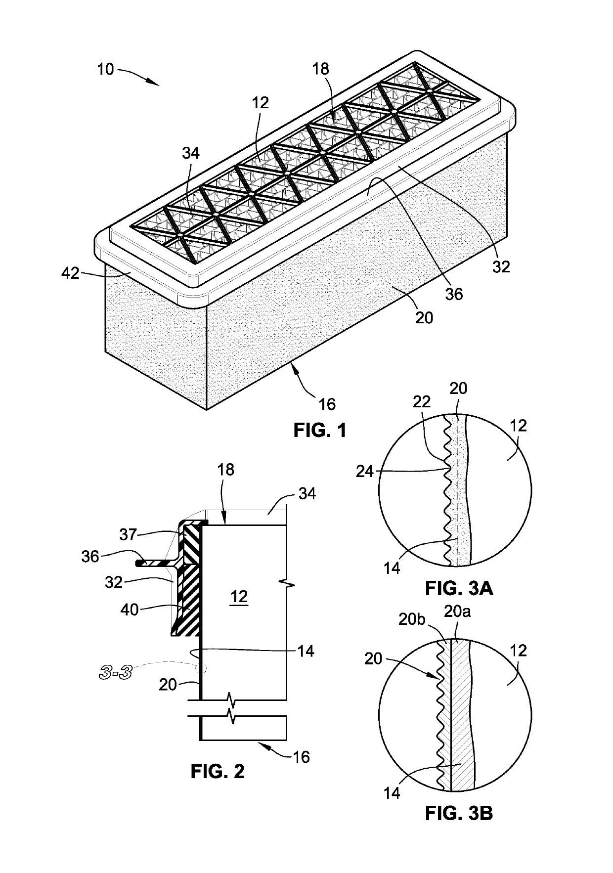
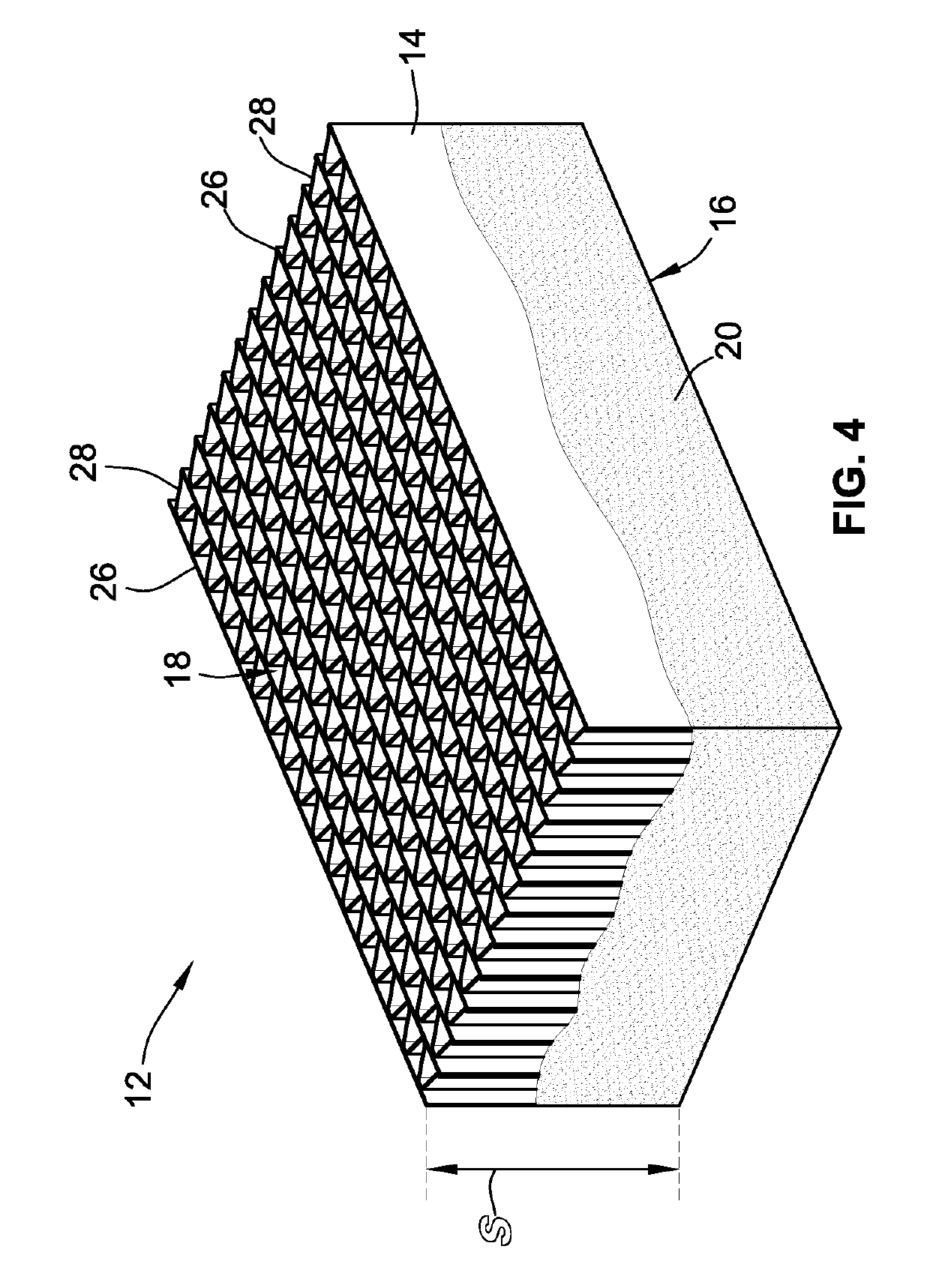
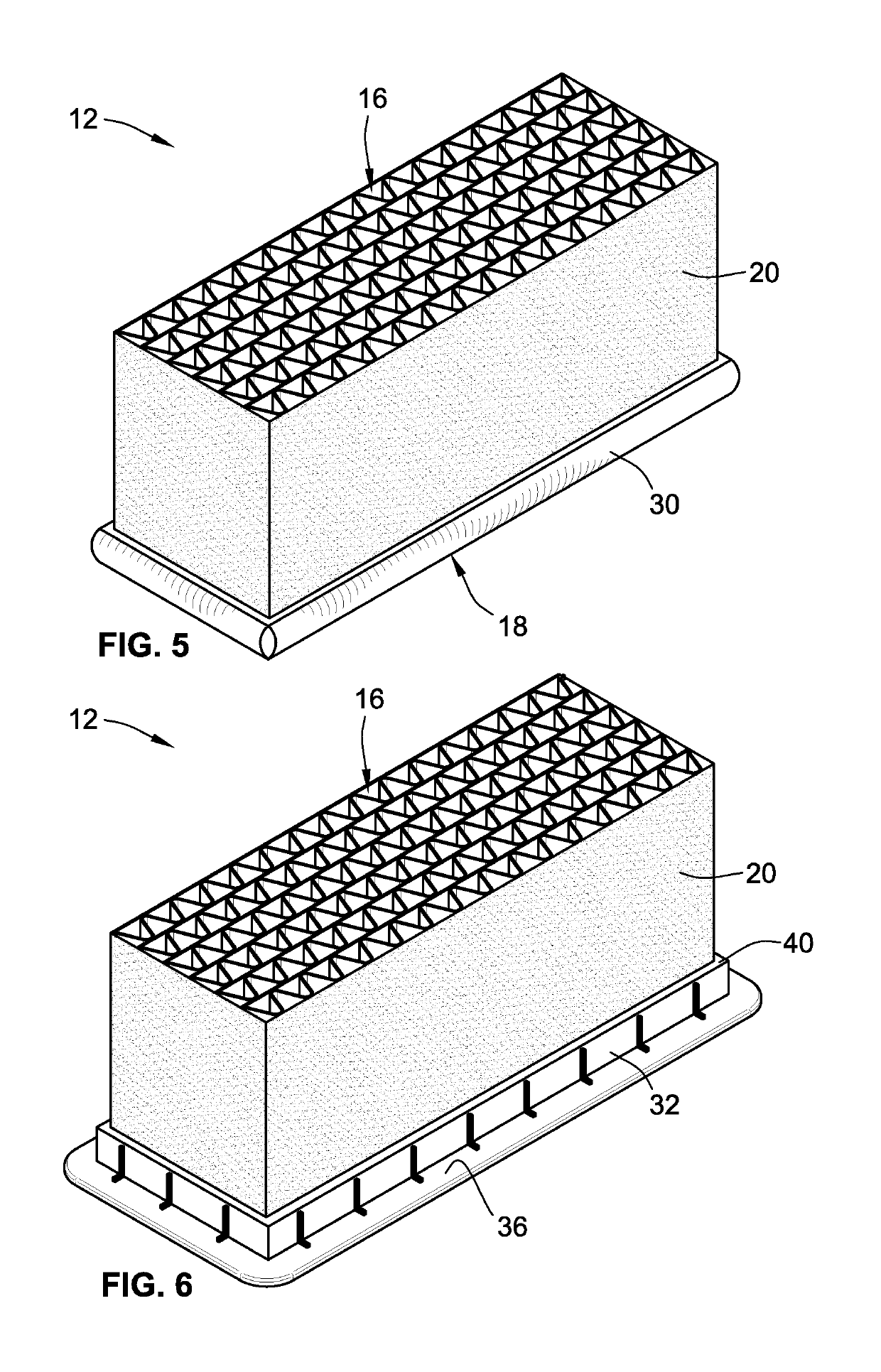
[0090]FIG. 1 depicts a filter element 10 according to one embodiment. The filter element 10 includes a filter media pack 12 having an outer surface 14 (shown in FIG. 2). The outer surface 14 extends between a first flow face 16 and a second flow face 18. The outer surface 14 of the media pack 12 is at least partially covered with a polymeric coating 20. Advantageously, the polymeric coating 20 is not a molded structure and, therefore, requires no mold tooling, which can be expensive to make for various sizes and to maintain. Instead, in preferred embodiments the polymeric coating 20 is applied directly to the outer surface 14 of the filter media pack 12 as a liquid, or other flowable / fluid material, that cures or hardens into a solid coating or layer.

[0091]The filter media pack 12 includes filter media for removing particulate from a fluid stream. In some instances, the filter media forms the outer surface 14 of the filter media pack 12. Additionally, the filter element 10 can be fo...


PUM

PropertyMeasurementUnit
humidityaaaaaaaaaa
diameteraaaaaaaaaa
diameteraaaaaaaaaa

Abstract

A filter element is provided. The filter element includes a filter media pack including an outer surface. The outer surface extending between a first flow face and a second flow face. The filter element also includes a polymeric coating applied to the outer surface of the filter media pack, wherein the polymeric coating is not a molded structure. In embodiments, the polymeric coating covers at least 25% of a span between the first flow face and the second flow face and has an average thickness of between 0.005 and 0.100 in. In other embodiments, the polymeric coating has a surface roughness of at least 50 μin to provide an outer gripping surface. A method and system for applying the polymeric coating to the filter element are also provided.

Description

FIELD OF THE INVENTION[0001]This invention generally relates to filters, and more particularly, to a coating of the exterior surface of a filter media pack.BACKGROUND OF THE INVENTION[0002]Filter media packs are often wrapped with a fabric or paper to enhance the aesthetics of the block of filter media as well as to protect the filter media during handling. Conventionally, the paper wraps are heavy cardstock, and the fabric wraps are polyester non-wovens. These wraps provide some reinforcement for the filter media packs, but they do not protect the filter media from puncturing if dropped or gouged during handling or installation. Additionally, these wraps do not provide strong bonding surfaces for attaching structures, such as seal members or mounting frames, which allows the attached structures to easily tear off. Further, these wraps are often difficult to bind to the filter media, which creates leak paths around the filter media pack.[0003]In some instances, the filter media is n...

Claims


Application Information

Patent Timeline
Patent Type & Authority Applications(United States)
IPC IPC(8): B01D46/52
CPCB01D46/525B01D46/0004B01D46/008B01D25/001B01D46/52B01D46/0002B01D46/88
Inventor KRULL, TIMOTHY L.EPPERSON, MATTHEW K.POKORNEY, DANIEL P.VON SEGGERN, MICHAEL J.
Owner BALDWIN FILTERS
Why Eureka
Try Eureka