Fluid supply assembly for removing gas bubbles from a fluid path
- Summary
- Abstract
- Description
- Claims
- Application Information
AI Technical Summary
Benefits of technology
Problems solved by technology
Method used
Image

Examples
first embodiment
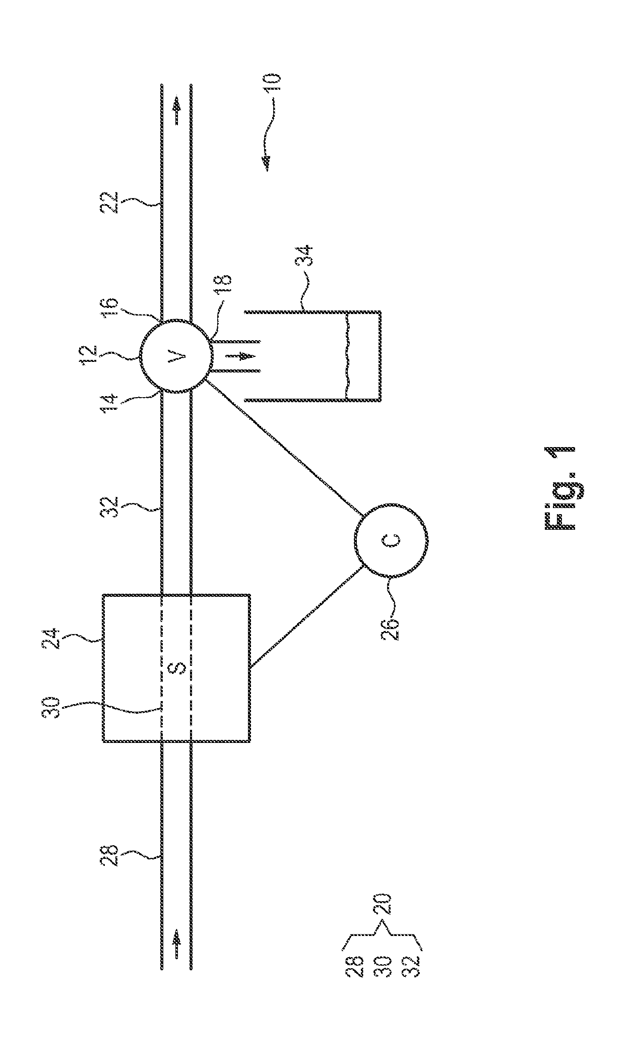
[0125]FIG. 1 shows a fluid supply assembly 10. The fluid supply assembly 10 comprises a multi-way valve unit 12, a first fluid path 20 and a second fluid path 22. The multi-way valve unit 12 comprises an inlet 14, a first outlet 16 and a second outlet 18. The first fluid path 20 is in fluid connection with the inlet 14 of the multi-way valve unit 12 in order to feed fluid from a product tank 58 (not shown) to the multi-way valve unit 12. The second fluid path 22 is in fluid connection with the first outlet 16 of the multi-way valve unit 12 in order to discharge fluid from the multi-way valve unit 12 to a filling device 50 (not shown). A collecting container 34 is arranged underneath the second outlet 18 to collect the fluid being discharged.
[0126]The fluid supply assembly 10 furthermore has a first sensor 24. The first fluid path 20 is divided into three portions which are arranged one behind the other in the flow direction of the fluid along the first fluid path. These are a first ...
second embodiment
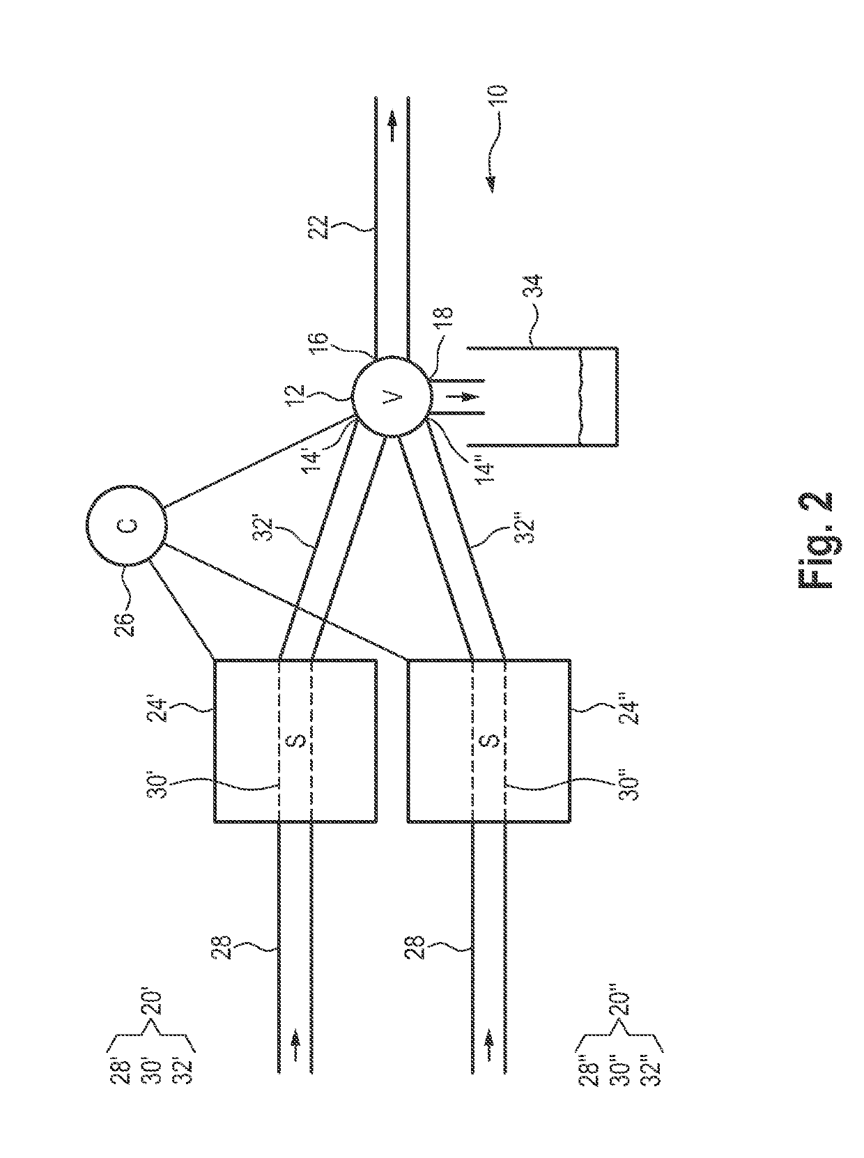
[0128]FIG. 2 shows a fluid supply assembly 10. The fluid supply assembly 10 comprises a multi-way valve unit 12, a first upper fluid path 20′, a first lower fluid path 20″ and a second fluid path 22. The multi-way valve unit 12 comprises a first inlet 14′, a second inlet 14″, a first outlet 16 and a second outlet 18. The upper first fluid path 20′ is in fluid connection with the first inlet 14′ in order to feed fluid from a product tank 58 (not shown) to the multi-way valve unit 12. The lower first fluid path 20″ is in fluid connection with the second inlet 14″ of the multi-way valve unit 12 in order to feed fluid from the product tank 58 (not shown) to the multi-way valve unit 12. The second fluid path 22 is in fluid connection with the first outlet 16 of the multi-way valve unit 12 in order to discharge fluid from the multi-way valve unit 12 to a filling unit 50 (not shown). Underneath the second outlet 18 of the multi-way valve unit 12 is a collecting container 34 in order to col...
third embodiment
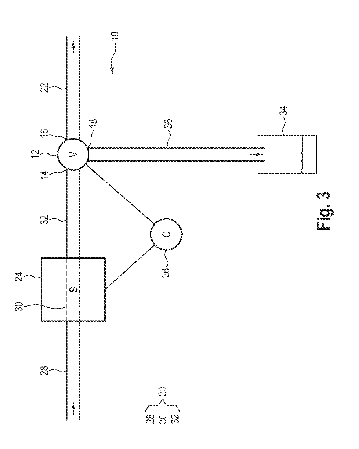
[0132]FIG. 3 shows a fluid supply assembly 10. The fluid supply assembly 10 has a multi-way valve unit 12, a first fluid path 20, a second fluid path 22 and a third fluid path 36. The multi-way valve unit 12 has an inlet 14, a first outlet 16 and a second outlet 18. The first fluid path 20 is in fluid connection with the inlet 14 of the multi-way valve unit 12 in order to feed fluid from a product tank 58 (not shown) to the multi-way valve unit 12. The second fluid path 22 is in fluid connection with the first outlet 16 of the multi-way valve unit 12 in order to discharge fluid from the multi-way valve unit 12 to a filling unit 50 (not shown). The third fluid path 36 is in fluid connection with the second outlet 18 of the multi-way valve unit 12 in order to discharge fluid from the multi-way valve unit 12 into a collecting container 34. The collecting container 34 is arranged underneath an open end of the third fluid path 36, The third fluid path 36 can more particularly be introduc...
PUM
| Property | Measurement | Unit |
|---|---|---|
| Time | aaaaa | aaaaa |
| Time | aaaaa | aaaaa |
| Length | aaaaa | aaaaa |
Abstract
Description
Claims
Application Information
PatSnap Eureka turns technology decisions into work you can execute. Powered by our Innovation Knowledge Graph, it runs expert workflows across engineering, life sciences, materials and intellectual property. Get your review-ready output in minutes.


